MN-553 • (091210) • ECR 7435 Kit No. 57275 & 57285 INSTALLATION GUIDE For maximum effectiveness and safety, please read these instructions completely before proceeding with installation. Failure to read these instructions can result in an incorrect installation.
LoadLifter 5000 2 MN-553
LoadLifter 5000 TABLE OF CONTENTS Introduction . . . . . . . . . . . . . . . . . . . . . . . . . . . . . . . . . . . . . . . 2 Important Safety Notice . . . . . . . . . . . . . . . . . . . . . . . . . . . . . . . . . . . . . . . . . . . . . 2 Notation Explanation . . . . . . . . . . . . . . . . . . . . . . . . . . . . . . . . . . . . . . . . . . . . . . . . 2 Installation Diagram . . . . . . . . . . . . . . . . . . . . . . . . . . . . . . . . 3 Hardware List . . . . . . . . . . . . . . . . . . . . . . . .
LoadLifter 5000 Introduction The purpose of this publication is to assist with the installation, maintenance and troubleshooting of the LoadLifter 5000 air spring kit. LoadLifter 5000 utilizes sturdy, reinforced, commercial grade single or double, depending on the kit, convolute bellows. The bellows are manufactured like a tire with layers of rubber and cords that control growth.
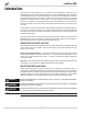
LoadLifter 5000 Installation Diagram 2500 HD Model, Driver Side Shown *The 3500 model has a different style strike plate. H G J K J B J J E L L D I A H I L, only on 2500 HD model C O O N Q J M P F Small weld nut bracket must be removed. Only on 2500 HD model. J L MN-553 U, only on 2500 HD model fig.
LoadLifter 5000 HARDWARE LIST Item A1 A2 B C D E F G H I J K L M N Part # 58437 58491 07634 03633 11951 21848 10451 17203 17108 17141 18444 18427 18435 18438 10465 Description................................Qty Air spring (57275) ...............................2 Air spring (57285) ...............................2 Upper bracket .....................................2 Lower bracket .....................................2 Roll plate .............................................4 Elbow fitting ...............
LoadLifter 5000 3. Install the upper bracket (B) onto the bellow assembly. Use slot “A” when installing on the driver’s side and use slot “B” when installing on the passenger’s side. Attach using two 3/8” bolts (G), lock washers (K), and flat washers (J). Leave the bolts loose at this time (fig. 2 and fig. 3). 4. Driver’s Side Only: Insert a 5/16” bolt (O) into the small hole on the lower bracket (C) before attaching the lower bracket to the air spring assembly (fig. 2). 5.
LoadLifter 5000 REMOVING THE JOUNCE BUMPER 1. Jack up the rear of the vehicle and support the frame with jack stands. Drop the axle to gain clearance to install the assembly. 2. Remove both jounce bumpers under the frame rail and discard. POSITIONING THE ASSEMBLY ON THE AXLE NOTE On the 2500 HD models only, the driver side axle may have a small bracket with a nut that has nothing attached to it. This bracket must be trimmed off of the axle in order to install the assembly (fig. 4). 2500 HD Models: 1.
LoadLifter 5000 ATTACHING THE UPPER BRACKET 1. The elbow fitting points toward the rear of the vehicle on the driver side and toward the front of the vehicle on the passenger side. 2. Insert two 3/8” bolts (H) and flat washers (J) through the existing jounce bumper holes and through the slotted holes in the upper bracket (fig. 6). NOTE It may be helpful to raise the axle at this point so that the upper bracket touches the frame. 3.
LoadLifter 5000 5. Attach the axle strap (F) to both lower bracket carriage bolts using two flat washers (J) and two nyloc nuts (L). Torque evenly to 16 ft/lbs (fig. 8). Axle strap fig. 8 Flat washer Nyloc nut INSTALLING THE EMERGENCY BRAKE LINE BRACKET AND CLIP (DRIVER SIDE ONLY) 1. Attach the brake line bracket (Q) to the lower bracket using the previously installed 5/16” bolt (O) with one flat washer (J) and a nyloc nut (M) (fig. 9). 2.
LoadLifter 5000 INSTALLING THE AIR LINES 1. Choose a convenient location for mounting the inflation valves. Popular locations for the inflation valve are: a. The wheel well flanges. b. License plate recess in bumper. c. Under the gas cap access door. d. Through license plate itself. NOTE What ever the chosen location is, make sure there is enough clearance around the inflation valves for an air chuck. 2. Drill a 5/16” hole to install the inflation valves. 3.
LoadLifter 5000 6. Route the air line along the frame to the air fitting on the air spring (fig. 14). Keep AT LEAST 6” of clearance between the air line and heat sources, such as the exhaust pipes, muffler, or catalytic converter. Avoid sharp bends and edges. Use the plastic tie straps (BB) to secure the air line to fixed, non-moving points along the chassis. Be sure that the tie straps are tight, but do not pinch the air line.
LoadLifter 5000 Before Operating INSTALLATION CHECKLIST Clearance test — Inflate the air springs to 60 PSI and make sure there is at least ½” clearance from anything that might rub against each sleeve. Be sure to check the tire, brake drum, frame, shock absorbers and brake cables. Leak test before road test — Inflate the air springs to 30 PSI and check all connections for leaks. Refer to “Checking for Leaks” on page 10. All leaks must be eliminated before the vehicle is road tested.
LoadLifter 5000 Maintenance and Servicing Minimum Air Pressure Maximum Air Pressure 5 PSI 100 PSI FAILURE TO MAINTAIN CORRECT MINIMUM PRESSURE (OR PRESSURE PROPORTIONAL TO LOAD), BOTTOMING OUT, OVER-EXTENSION OR RUBBING AGAINST ANOTHER COMPONENT WILL VOID THE WARRANTY. MAINTENANCE GUIDELINES NOTE By following these steps, vehicle owners will obtain the longest life and best results from their air spring. 1. Check the air pressure weekly. 2. Always maintain normal ride height.
LoadLifter 5000 Product Use FREQUENTLY ASKED QUESTIONS Q. Will installing air springs increase the weight ratings of a vehicle? No. Adding air springs will not change the weight ratings (GAWR, GCWR and/or GVWR) of a vehicle. Exceeding the GWVR is dangerous and voids the Air Lift warranty. Q. Is it necessary to keep air in the air springs at all times and how much pressure will they need? The minimum air pressure should be maintained at all times.
LoadLifter 5000 GUIDELINES FOR ADDING AIR 1. Start with the vehicle level or slightly above. 2. When in doubt, always add air. 3. For motorhomes, start with 50-100 PSI in the rear because it can be safely assumed that it is heavily loaded. 4. If the front of the vehicle dives while braking, increase the pressure in the front air bags, if equipped. 5. If it is ever suspected that the air bags have bottomed out, increase the pressure (fig. 18). 6. Adjust the pressure up and down to find the best ride. 7.
LoadLifter 5000 Warranty and Returns Policy continued Air Lift 1000 .................... Lifetime Limited RideControl .................... Lifetime Limited SlamAir ........................... Lifetime Limited LoadLifter 5000*............. Lifetime Limited Air Lift Performance** ...... 1 Year Limited Load Controller (I) ............ 2 Year Limited Load Controller (II) ........... 2 Year Limited SmartAir ............................ 2 Year Limited Wireless AIR......................
LoadLifter 5000 Notes 16 MN-553
LoadLifter 5000 Notes MN-553 17
Need Help? Contact our customer service department by calling (800) 248-0892, Monday through Friday, 8 a.m. to 8 p.m. Eastern Time. For calls from outside the USA or Canada, our local number is (517) 322-2144. Register your warranty online at www.airliftcompany.