Kit 57345 Ford F-450, F-550 MN-520 • (071703) • ECR 8760 Cover illustration may not depict actual kit. INSTALLATION GUIDE For maximum effectiveness and safety, please read these instructions completely before proceeding with installation. Failure to read these instructions can result in an incorrect installation.
TABLE OF CONTENTS Introduction. . . . . . . . . . . . . . . . . . . . . . . . . . . . . . . . . . . . . . . . . . . 2 Important Safety Notice . . . . . . . . . . . . . . . . . . . . . . . . . . . . . . . . . . . . . . . . . . . . . . . . . . . . . 2 Notation Explanation. . . . . . . . . . . . . . . . . . . . . . . . . . . . . . . . . . . . . . . . . . . . . . . . . . . . . . . . 2 Installation Diagram. . . . . . . . . . . . . . . . . . . . .
LoadLifter 5000 Introduction The purpose of this publication is to assist with the installation, maintenance and troubleshooting of the LoadLifter 5000 air spring kit. LoadLifter 5000 utilizes sturdy, reinforced, commercial grade single or double, depending on the kit, convolute bellows. The bellows are manufactured like a tire with layers of rubber and cords that control growth.
LoadLifter 5000 Installation Diagram G AA Passenger side view N J E I L NOTE: Some late model frames do not have existing holes and will need to be drilled. M On both the passenger’s side and the driver side, the rear, bottom hole is not pre-drilled. D A D C Forward H I J N I O F fig.
LoadLifter 5000 Hardware List and Tools List HARDWARE LIST Item Part # Description................................Qty A B C D E F G H I J L M 58115 07460 03260 11897 18467 10594 21830 18435 18444 18427 18466 17255 Air spring..............................................2 Upper bracket......................................2 Lower bracket......................................2 Roll plate..............................................4 7/16”-14 Nylon lock nut ......................8 3/8”-16 x 2” U-bolt...
LoadLifter 5000 a. Remove unusual loads and examine your vehicle from the side to ensure it is on a level surface. b. If necessary (in cases where your leaf springs are sagging badly), use a jack to raise the rear end so that the vehicle achieves the original “as delivered” ride height. 2. Measure the distance between the center of the hub and the bottom edge of the wheel well (Fig. 2). This is the normal ride height. The distance from one end of the arrow to the other is normal ride height. 9” fig.
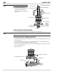
LoadLifter 5000 NOTE Remember that the legs face down. 6. Loosely attach the lower bracket to the assembly using 3/8” flat washers (I), lock washers (J), and hex-head bolts (N) (Fig. 4). Lock washer (J) Flat washer (I) 90° swivel air fitting (G) Hex-head bolt (N) Upper bracket (B) Air spring (A) Roll plates (D) Lower bracket (C) fig. 4 Flat washer (I) Lock washer (J) Hex-head bolt (N) POSITIONING THE BRACKETS 1. Set the air spring assembly on the leaf spring over the axle (Fig.
LoadLifter 5000 INSTALLING THE UPPER BRACKET NOTE FOR DRIVER’S SIDE ONLY: It will be necessary to remove the bolt holding the emergency brake cable bracket. CAUTION NOTE BEFORE DRILLING, CHECK THE BACK SIDE OF THE FRAME FOR CLEARANCE ISSUES WITH THE BRAKE LINES, GAS LINES, AND ELECTRICAL LINES. ANY OBSTACLES WILL NEED TO BE TEMPORARILY RELOCATED TO CLEAR THE AREA. Most or all of the existing holes and slots in the frame do not exist on 2008 or later models. They must be drilled on these vehicles.
LoadLifter 5000 Align the air spring so that it is uniformly positioned between the upper and lower bracket. Minimum thumbs width clearance between the air spring and the frame. fig. 8 SECURING THE AIR SPRING TO THE BRACKETS NOTE Push the roll plate outboard before tightening the lower bracket. 1. Secure the air spring to the lower brackets using an open-ended 9/16” wrench by tightening the two bolts on the bottom of the spring assembly. 2.
LoadLifter 5000 Installing the Air Lines This section explains how to set up the air spring kit to be controlled with Schrader valves and a separate compressed air source. An on-board air compressor system allows for hassle-free control of the air springs. Learn more about Air Lift control systems at www.airliftcompany.com/products/compressor-systems. 1. Choose a convenient location for mounting the inflation valves (Fig. 9). Popular locations for the inflation valve are: a. The wheel well flanges b.
LoadLifter 5000 TIPS FOR INSTALLING AIR LINES When cutting air lines, use a sharp knife or a hose cutter and make clean, square cuts (Fig. 11). Do not use scissors or wire cutters because these tools may deform the air line, causing it to leak around fittings. Do not cut the lines at an angle. Do not bend the 1/4” hose at a radius of less than 1” or bend the 3/8” hose at a radius of less than 1 1/2”. Do not put side load pressure on fitting.
LoadLifter 5000 Before Operating CHECKING FOR LEAKS 1. Inflate the air spring to 30 PSI. 2. Spray all connections and the inflation valves with a solution of 1/5 liquid dish soap and 4/5 water. Spot leaks easily by looking for bubbles in the soapy water. 3. After the test, deflate the springs to the minimum pressure required to restore the system to normal ride height. Do not deflate to lower than 5 PSI. 4. Check the air pressure again after 24 hours. A 2-4 PSI loss after initial installation is normal.
LoadLifter 5000 INSTALLATION CHECKLIST Clearance test — Inflate the air springs to 75-90 PSI and make sure there is at least 1/2” clearance from anything that might rub against each sleeve. Be sure to check the tire, brakes, frame, shock absorbers and brake cables. Leak test before road test — Inflate the air springs to 75-90 PSI and check all connections for leaks. All leaks must be eliminated before the vehicle is road tested.
LoadLifter 5000 Product Use, Maintenance and Servicing Minimum Recommended Pressure Maximum Air Pressure 5 PSI 100 PSI MAINTENANCE GUIDELINES NOTE By following the steps below, vehicle owners will obtain the longest life and best results from their air springs. 1. Check air pressure weekly. 2. Always maintain normal ride height. Never inflate beyond 100 PSI. 3.
LoadLifter 5000 TUNING THE AIR PRESSURE Pressure determination comes down to three things — level vehicle, ride comfort and stability. 1. Level vehicle If the vehicle’s headlights are shining into the trees or the vehicle is leaning to one side, then it is not level (Fig. 14). Raise the air pressure to correct either of these problems and level the vehicle. 2. Ride comfort If the vehicle has a rough or harsh ride it may be due to either too much pressure or not enough (Fig. 15).
LoadLifter 5000 Troubleshooting Guide PROBLEM CAUSE SOLUTION System won’t maintain pressure overnight. Improperly installed air line, air line has holes or cracks. Leak test the air line connections, the threaded connection into the air spring, and all fittings in the control system. Air spring or air line leak. Fitting seal or air line is compromised. Check to make sure air lines are seated in connectors. Inspect fittings with soapy water. Trim hose or re-seal fitting.
LoadLifter 5000 Notes 16 MN-520
LoadLifter 5000 Limited Warranty and Return Policy Air Lift Company provides a limited lifetime warranty to the original purchaser of its Load Support products, that the products will be free from defects in workmanship and materials when used on cars and trucks as specified by Air Lift Company and under normal operating conditions, subject to the requirements and exclusions set forth in the full Limited Warranty and Return Policy that is available online at www.airliftcompany.com/warranty.
Need Help? Contact Air Lift customer service department by Contact AirCompany Lift Company customer service calling (800) 248-0892. department by the calling For calls from outside USA or (800) Canada,248-0892. dial (517) 322-2144. For calls from outside the USA or Canada, dial (517) 322-2144. Thank you for purchasing Air Lift products — the professional installer’s choice! Air Lift Company • 2727 Snow Road • Lansing, MI 48917 or P.O.