
Owner's manual


A I R B A G I T. C O M S U S P E N S I O N S
2 6 0 S . H I B B E R T, M E S A , A Z P H . 8 0 0 - 8 4 2 - 8 7 8 9
Smart Ride
COMPLETE DIGITAL AIR MANAGEMENT SYSTEM
Smart Ride
COMPLETE DIGITAL AIR MANAGEMENT SYSTEM
Installation and operating
instructions
Installation and operating
instructions
Index
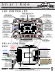
LCD Controller and Relay Control Box Layouts
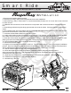
Plug n Play Installation
Non-Plug n Play Installation
Non-Plug n Play Schematic
Air-Engine / Air Force Wiring Schematics
Height Sensor Installation
Preset and Compressor Setup and Functionality Tips (Setup Screen #1)
Timing, Pressure Switch and Tolerance Setup (Setup Screen #2)
Height Sensor Calibration (Setup Screen #3 and #4)
Optional Input Wiring Schematic
Page
1
2
3
4
5
6-8
9
10
11
12
The System Includes
Smart-Ride Standard
LCD Controller
Relay Control Box
Power Loom
Valve Loom
Smart-Ride P and Smart-Ride HP
300 PSI Digital Pressure Sender w/18” Loom (Optional 240” Loom)
Spanner Wrench
Smart-Ride H and Smart-Ride HP
Height Sensors w/240” Looms
Smart-Ride HP Hardware Pack
Ball Joints
1/4-28 x 12” Threaded Rod
1/4-28 Hex Nuts
1/4-28 Nyloc Nuts
QTY
1
1
1
1
5
1
4
1
8
4
8
8