IBIS ROOFTOP AIRCONDITIONER OWNER’S MANUAL Pantone Cool Grey 9U Pantone 301 U Pantone DS196 - 4 U (Alternative) • • • • • Installation Instructions Commissioning of IBIS after installation Possible faults and remedy Specifications Warranty Conditions • • • • • Notice d’installation Mise en service d’IBIS après l’installation Défauts éventuels et solutions Spécifications Conditions de garantie • • • • • Einbauanleitung Inbetriebnahme des IBIS nach dem Einbau Mögliche Probleme und ihre Behebung Spezif
WARRANTY OF REFRIGERATED AIRCONDITIONING Warranty within Australia We undertake by this warranty to rectify, free of charge, at our nearest authorised service agent, any fault due to faulty workmanship or replacement of any faulty components within 12 months from the date of the first retail purchase thereof.
CUSTOMER’S COPY Purchaser’s Name ............................................................................................................................................................................................................................. Address ................................................................................................................................................................................................................................................ ........
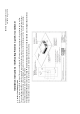
14 inch square hole REAR OF UNIT DIRECTION OF TRAVEL CALL AIRCOMMAND FOR ADVICE IF YOUR INSTALLATION DIFFERS SIGNIFICANTLY DISTANCES SHOWN ARE CALCULATED FROM A 14” SQUARE HOLE (356X356MM) THE OUTLINE SHOWS THE MINIMUM CLEARANCE REQUIRED AROUND THE IBIS ROOF UNIT FRONT OF UNIT DIRECTION OF TRAVEL MINIMUM 25MM CLEARANCE FROM SIDE GRILL TO ANY OBSTRUCTION IMPORTANT NOTE: FRONT OF UNIT MUST FACE DIRECTION OF TRAVEL FAILURE TO FOLLOW THIS INSTRUCTION WILL RESULT IN DAMAGE TO CONDENDER FANS MINIMUM 200
1. Roof strength • The roof members MUST be strong enough to support the weight of the airconditioner (up to 50kg) without any roof deflection that will cause ‘pooling’ of water around the unit. • If in any doubt as to the strength of the roof then consider the use of an external ‘H” frame. Contact Aircommand for further details.
Front of Caravan 2. Install self adhesive gasket 1. The roof area must be clean and dry and free from grease or oil 2. Remove paper backing from the roof sealing gasket and position over square hole as shown 3. Gasket must be applied with the self adhesive side down. Note orientation of gasket to direction of travel. 4. Press gasket down firmly to ensure good adhesion 5.
2. Position IBIS roof top air conditioner over the gasket 1. Position the unit on the gasket so that the corners of square hole in the caravan roof line up with the corners of the square hole under the air conditioning unit. 2.
Blue A Brown 15 Amp power inlet 15 Amp 2 pole RCD Minimum contact gap of 3mm in OFF position cable min. area 1.5 squ.
5. Assemble duct 1. Thread a hold-down bar onto the M8 bolt and push the bolt almost all the way into the hole at each corner. Leave a 10mm gap between the hold-down bar and the recess in the plastic brace. This will allow easier engagement with the 4 corresponding threaded holes in the roof top unit 2. Repeat for all four corners 3. Add black plastic duct to the top of the assembly with the notch upwards.
6. Attach duct to unit • Raise duct assembly and engage the flexible black plastic duct on the outside diameter of the outlet from the roof top unit. Ensure that key hole cut out in the flexible duct aligns with the inside fan's power cable • Engage and tighten the four M8 bolts with the threaded insets in the roof top unit.
• Connect key pad cable to control cable. Note that wire colour should correspond (yellow to yellow, red to red etc) 7. Attach Main Cover of Plenum • Suspend the main cover from the duct by attaching the blue cord to the lug on the inside of main cover. This will allow you to use both hands to connect the control cable.
Remove the filter units and use the six counter sunk self tapping screws to secure the main covers edge to the caravan ceiling Replace filters • • Installation is complete Raise the main cover up so that it engages with the duct assembly and secure the main cover to the duct with 4 screws provided • IBIS Mk II Installation Instruction 6/8/2010 Page 9 of 9
COMMISSIONING OF THEOFIBIS AFTER INSTALLATION COMMISSIONING THE IBIS AFTER INSTALLATION Check OK 1. TurnTurn on power at the circuit breaker or ECB. on power at the circuit breaker or ECB. 2. Press the the ON/OFF button. The. The display should illuminate. Press ON/OFF button display should illuminate 3. Press MODE button andand cycle to enter the the cooling mode. TheThe “COOL” LED LED will will illuminate Press MODE button cycle to enter cooling mode. “COOL” illuminate 4.
SPECIFICATIONS Electrical rating Nom. Cooling capacity Nom. Heating Capacity Max rated current cooling Max rated current heating L/R Amps Inside air delivery Installed weight 240 V 50 Hz 3.2 KW 3.2 KW 5.4 Amps 5.6 Amps 20 Amps 140 l/s 49 Kg Overall height Overall width Overall length 220 mm 825 mm 1040 mm Inside plenum height Inside plenum width Inside plenum length Plenum weight 65 mm 535 mm 555 mm 2.
POSSIBLE FAULTS AND REMEDY Control Pad will not illuminate when ON/OFF button is depressed • Check power supply to van OK • Check circuit breaker is on • Control cable may be unplugged between outside unit and inside facia. Unit does not cool • Ensure mode button has the green cool LED Illuminated constantly • Thermostat set point must be below room temperature NB: The compressor has a 3 minute delay to start and so may not start immediately. Unit does not heat.
ARRIERE DE L’APPAREIL DIRECTION DE LA MARCHE TROU CARRÉ DE 14 POUCES (35 CM) ARRIERE DE L’APPAREIL DIRECTION DU DEPLACEMENT DIRECTION DU DEPLACEMENT DE NT IL AVA PARE L’AP CONTACTER AIRCOMMAND SI VOTRE INSTALLATION DIFFERE SIGNIFICATIVEMENT DE CELLE-CI LES DISTANCES INDIQUÉES SONT CALCULEES SUR LA BASE D’UN TROU CARRÉ DE 356MM X 356MM CE PLAN MONTRE L’ESPACE MIN. REQUIS AUTOUR DE L’APPAREIL DE TOIT IBIS ESPACE MIN.
1. Solidité du toit • Les membres du toit DOIVENT être assez solides pour soutenir le poids du climatiseur (jusqu'à 50 kg) sans fléchissement du toit, ce qui causerait l’accumulation d’eau autour de l’appareil. • En cas de doute quant à la solidité du toit, envisager l’utilisation d’un cadre externe en H. Contacter Aircommand pour plus de détails.
Avant de la caravane 2. Poser le joint d’étanchéité autocollant 1. La surface du toit doit être propre et sèche et exempte de graisse ou d’huile. 2. Enlever le fond papier du joint d’étanchéité de toit et le placer sur le trou carré comme indiqué 3. Le joint d’étanchéité doit être appliqué avec l’autocollant orienté vers le bas. 4. Appuyer fermement sur le joint d’étanchéité pour obtenir une bonne adhésion. 5.
2. Positionner le climatiseur de toit IBIS sur le joint d’étanchéité 1. Positionner l’unité sur le joint d’étanchéité de sorte que les coins du trou carré du toit de la caravane s’alignent avec les coins du trou carré sous le climatiseur. 2. Les quatre trous de montage M8 situés sur le châssis du climatiseur s’aligneront avec les coins du trou carré dans le toit.
Bleu A Marron Prise électrique de 15 Amp RCD à 2 pôles 15 A Espace de contact min. de 3 mm en position arrêt Câble rigide – surface min. 1,5 mm2 7 fils min Longueur de boulons d’ablocage requise (mm) Tel que fourni Tel que fourni Tel que fourni Couper 50 Couper 70 Couper 85 Longueur de conduit requise (mm) 150 (tel que fourni) 125 (couper 25) 105 (couper 45) 85 (couper 65) 65 (couper 85) 50 (couper 100) NOTA: Si la longueur du conduit doit être ajustée, couper l’excès de l’extrémité sans encoche.
5. Assembler le conduit 1. Introduire une barre de retenue dans le boulon M8 et enfoncer le boulon presque complètement dans le trou de chaque coin. Laisser un espace de 10mm entre la barre de retenue et le retrait dans le renfort en plastique. Ceci facilitera le positionnement sur les 4 trous filetés correspondants sur l’unité de toit. 2. Répéter pour les quatre coins. 3. Placer le conduit en plastique noir sur le haut de l’assemblage en orientant l’encoche vers le haut.
6. Fixer le conduit à l’appareil • Soulever l’ensemble du conduit en plastique noir flexible et l’accoupler au diamètre externe de la décharge de l’unité de toit. Veiller à ce que la découpe en trou de serrure du conduit flexible s’aligne avec le câble électrique du ventilateur. • Engager les quatre boulons M8 dans les inserts filetés de l’unité de toit et les serrer. Le couple de serrage recommandé est 7 Nm.
• Connecter le câble du pavé numérique au câble de commande. Noter que la couleur des fils doit correspondre (jaune à jaune, rouge à rouge, etc.) 7. Fixer le couvercle principal du plenum • Suspendre le couvercle principal au conduit en fixant le cordon bleu à l’oreille de fixation à l’intérieur du couvercle principal. Cela vous permettra d’utiliser vos deux mains pour connecter le câble de commande.
Retirer les unités filtres et fixer le rebord du couvercle principal au plafond de la caravane à l’aide des six vis autotaraudeuses à tête fraisée. Remplacer les filtres • • L’installation est terminée Soulever le couvercle principal pour qu’il s’emboite sur le conduit et le fixer au conduit avec les 4 vis prévues à cet effet.
MISE EN SERVICE DE L’IBIS APRES L’INSTALLATION COMMISSIONING OF THE IBIS AFTER INSTALLATION Vérification OK 1. Mettre l’appareil sous tension au coupe-circuit ou ECB. Turn on at the circuit(Marche/Arrêt). breaker or ECB. L’affichage devrait s’illuminer. 2. Appuyer surpower le bouton ON/OFF Press sur thele ON/OFF The display should illuminate 3. Appuyer boutonbutton MODE.et défiler pour entrer en mode de refroidissement. Le LED “COOL” s’illumine.
SPECIFICATIONS Caractéristiques assignées Capacité de refroidissement nom. Capacité de chauffage nom. Courant assigné max Courant assigné max Ampères G/D Soufflage interne Poids installé 240 V 50 Hz 3.2 KW 3.2 KW 5.4 Amps 5.6 Amps 20 A 140 l/s 49 Kg Hauteur hors tout Largeur hors tout Longueur hors tout 220 mm 825 mm 1040 mm Hauteur du plenum interne Largeur du plenum interne Longueur du plenum interne Poids du plenum 65 mm 535 mm 555 mm 2.
DÉFAUTS ÉVENTUELS ET SOLUTIONS Le boîtier de commande ne s’illumine pas quand le bouton ON/OFF est enfoncé • Vérifier l’alimentation de la caravane • Vérifier que le coupe-circuit est sous tension • Il est possible que le câble de commande reliant l’unité extérieure au panneau intérieur soit débranché L’appareil de rafraichit pas • Vérifier que le voyant DEL de refroidissement vert du bouton de mode reste illuminé • Le point de consigne du thermostat doit être au-dessous de la température ambiante NB : L
RÜCKSEITE DES GERÄTS FAHRTRICHTUNG Quadratischer Ausschnitt 356 x 356 mm ERSUCHEN SIE AIRCOMMAND UM BERATUNG, FALLS IHR EINBAU SICH BETRÄCHTLICH VON DIESEM UNTERSCHEIDET. DIE ENTFERNUNGEN SIND VOM QUADRATISCHEN AUSSCHNITT (356 X 356 MM) GERECHNET. DIESER AUFRISS ZEIGT DEN BENÖTIGTEN MINDESTFREIRAUM UM DAS IBIS DACHGERÄT. S DE ITE RSE S DE ERÄT R VO G FAHRTRICHTUNG MINDESTENS 25 MM FREIRAUM VON DER SEITE DES GRILLS BIS ZU JEDEM HINDERNIS.
1. Dachstärke • Die Dachträger MÜSSEN stark genug sein, um das Gewicht des Klimageräts (bis zu 50 kg) zu tragen, ohne dass sich das Dach verbiegt, da dies Wasserlachen im Umfeld des Geräts verursachen würde. • Sollten Sie irgendwelche Zweifel an der Tragfähigkeit des Daches hegen, erwägen Sie die Anwendung eines externen H-Rahmens. Bitte wenden Sie sich für weitere Einzelheiten an Aircommand.
Von der Karawane 2. Selbstklebende Dichtung anbringen 1. Die Dachträger MÜSSEN stark genug sein, um das Gewicht des Klimageräts (bis zu 50 kg) zu tragen, ohne dass sich das Dach verbiegt, da dies Wasserlachen im Umfeld des Geräts verursachen würde. 2. Papierstreifen von der Dachdichtung abziehen und die Dichtung, wie abgebildet, über dem quadratischen Loch platzieren. 3. Dichtung muss mit selbstklebender Seite nach unten aufgebracht werden. Ausrichtung der Dichtung relativ zur Fahrtrichtung beachten. 4.
2. IBIS Dachklimagerät über der Dichtung platzieren 1. Das Gerät so auf der Dichtung platzieren, dass die Ecken des quadratischen Ausschnitts im Wohnmobildach mit den Ecken des quadratischen Ausschnitts auf der Unterseite des Klimageräts bündig sind. 2. Die vier M8-Befestigungslöcher am Gehäuse des Klimageräts decken sich dann mit den Ecken des quadratischen Ausschnitts im Dach. IBIS Mk II Einbauanleitung 8.6.
P Braun 15 A Leistungsaufnahme RCD 15 A 2-polig Minimumkontaktabstand 3 mm bei AUS-Position Starres Kabel Mindeststärke 1,5 mm2 mindestens 7-adrig erforderliche Luftkanallänge (mm) 150 (wie Liefermaß) 125 (um 25 kürzen) 105 (um 45 kürzen) 85 (um 65 kürzen) 65 (um 85 kürzen) 50 (um 100 kürzen) erforderliche Länge der Befestigungsschrauben (mm) wie Liefermaß wie Liefermaß wie Liefermaß um 50 kürzen um 70 kürzen um 85 kürzen BITTE BEACHTEN - Falls die Länge des Luftkanals geändert werden muss, Überlänge
5. Montage des Luftkanals 1. Befestigungsplatte auf die Schraube M8 aufdrehen und die Schraube fast die gesamte Länge bis in das Eckloch drücken. Einen Abstand von 10 mm zwischen der Befestigungsplatte und der Ausbuchtung der Plastikmanschette belassen; dies erleichtert die Verbindung mit den 4 gegenüberliegenden Schraubenlöchern des Dachgeräts. 2. In allen vier Ecken wiederholen. 3. Schwarzen Plastikkanal mit der Kerbe nach oben auf die Baugruppe aufsetzen.
6. Kanal am Gerät anbringen • Die Baugruppe mit dem Luftkanal anheben und den flexiblen, schwarzen Plastikkanal am Außenrand des Ausgangs des Dachgeräts ansetzen. Vergewissern Sie sich, dass das in dem flexiblen Luftkanal ausgeschnittene Schlüsselloch auf das Kabel des Innenventilators ausgerichtet ist. • Führen Sie die vier Schrauben M8 in die Gewindelöcher im Dachgerät ein und ziehen sie diese an. Empfohlenes Anzugsmoment ist 7 Nm.
• Verstöpseln Sie das Kabel des Tastenfelds mit dem Steuerkabel. Beachten Sie dabei, dass die Kabelfarben übereinstimmen müssen (Gelb an Gelb, Rot an Rot usw.) 7. Anbringen der Hauptabdeckung des Luftschachts • Hängen Sie die Hauptabdeckung vom Luftkanal ab, indem Sie die blaue Kordel an der Öse auf der Innenseite der Hauptabdeckung befestigen. Dies ermöglicht Ihnen, beide Hände für den Anschluss des Steuerkabels frei zu haben. IBIS Mk II Einbauanleitung 8.6.
Entfernen Sie die Filter und benutzen Sie die sechs selbstschneidenden Senkkopfschrauben, um die Einfassung der Hauptabdeckung an der Wohnwagendecke zu befestigen. Filter wieder einsetzen. • Einbau ist beendet. • Heben Sie die Hauptabdeckung an, sodass sie auf der Baugruppe mit dem Luftkanal aufsitzt, und befestigen Sie die Hauptabdeckung mit den 4 mitgelieferten Schrauben am Luftkanal. • IBIS Mk II Einbauanleitung 8.6.
INBETRIEBNAHME DES IBIS NACH DEM EINBAU COMMISSIONING OF THE IBIS AFTER INSTALLATION Check OK 1. Strom am Schutzschalter oder Sicherungsautomaten einschalten. 2. ON/OFF-Knopf drücken. Die Anzeige sollte aufleuchten. Turn on power at the circuit breaker or ECB. 3. MODE-Knopf drücken und durchlaufen, um den Kühlmodus einzugeben. Die LED-Anzeige Press the ON/OFF button . The display should illuminate “COOL“ leuchtet auf. Press MODE button and cycle to enter the cooling mode.
SPEZIFIKATIONEN Elektrische Spannung und Frequenz Nennleistung Kühlen Nom. Heating Capacity Max. Nennstrom Kühlen Max. Nennstrom Heizen Anzugsstrom Luftzufluss innen Einbaugewicht 240 V 50 Hz 3.2 KW 3.2 KW 5.4 A 5.6 A 20 A 140 l/s 49 Kg Gesamthöhe Gesamtbreite Gesamtlänge 220 mm 825 mm 1040 mm Innenhöhe des Luftschachts Innenbreite des Luftschachts Innenlänge des Luftschachts Luftschachtgewicht 65 mm 535 mm 555 mm 2.
MÖGLICHE PROBLEME UND IHRE BEHEBUNG Bedienungsgerät leuchtet nicht, wenn ON/OFF-Knopf gedrückt wird. • Prüfen, dass Stromzufuhr zum Wohnmobil bzw. Wohnwagen in Ordnung ist. • Prüfen, dass Schutzschalter eingeschaltet ist. • Steuerkabel zwischen Außengerät und Innenarmatur vielleicht nicht eingesteckt. Gerät kühlt nicht. • Prüfen, ob die grüne LED-Kühlanzeige des MODE-Knopfes dauerhaft euchtet. • Einstellung des Thermostats muss unter Raumtemperatur liegen. NB.
PARTE POSTERIOR DE LA UNIDAD Agujero cuadrado de 14 pulgadas DIRECCIÓN DE VIAJE AVISO IMPORTANTE: EL FRENTE DE LA UNIDAD DEBE ENFRENTAR LA DIRECCIÓN DE VIAJE.
1. Resistencia del techo • Los miembros del techo DEBEN ser lo suficientemente resistentes para soportar el peso del acondicionador de aire (hasta 50 kg) para que no se produzca una deflexión del techo lo que causaría que se forme una “laguna” de agua alrededor de la unidad. • Si se tiene duda respecto a la resistencia del techo se debe entonces considerar el uso de un armazón externo en forma de “H”. Por mayores detalles, póngase en contacto con Aircommand.
Frente de la casa rodante 2. Instalar la junta auto adhesiva 1. La superficie del techo debe estar limpia y seca y libre de grasa o aceite 2. Remueve el papel de atrás de la junta selladora que va en el techo y colóquela sobre el agujero cuadrado según se muestra en la figura 3. La junta se debe colocar con la parte auto-adhesiva hacia abajo. Note la orientación de la junta hacia la dirección de viaje.. 4. Presione la junta firmemente hacia abajo para asegurar una buena adhesión 5.
2. Coloque el acondicionador de aire de techo IBIS sobre la junta 1. Coloque la unidad sobre la junta de manera que las esquinas del agujero cuadrado del techo de la casa rodante queden aliñadas con las esquinas del agujero inferior de la unidad del acondicionador de aire. 2.
Azul A Marrón 15 Amp alimentación de entrada 15 Amp 2 polos RCD Mínimo espacio de contacto de 3mm en la posición de apagado (OFF) Cable rígido superficie mínima 1.
5. Armado del conducto 1. Pase una barra de sujeción por el bulón M8 y empuje casi todo el bulón a través del orificio en cada esquina. Deje un espacio de 10 mm entre la barra de sujeción y el hueco en la abrazadera de plástico. Esto permitirá un enganche más fácil con los 4 orificios roscados en la unidad del techo 2. Repita este paso en las cuatro esquinas 3. Agregue el conducto de plástico negro en la parte superior con las ranuras hacia arriba.
6. Coloque el conducto en la unidad • Levante el conjunto del conducto y enganche el conducto flexible de plástico negro sobre el diámetro exterior de la salida de la unidad de techo. Asegúrese que el agujero cortado en el conducto flexible quede aliñado con el cable de alimentación del ventilador interior • Enganche y ajuste los cuatro bulones M8 en las roscas de la unidad del techo.
• Conecte la clavija del cable al cable de control. Note que el color del cable debe ser el mismo ( Amarillo con amarillo, rojo con rojo, etc.) 7. Coloque la Cubierta principal de la Cámara Suspenda la cubierta principal del conducto pasando el cordón azul por la orejeta que se encuentra dentro de la cubierta principal. Esto le permitirá usar las dos manos para conectar el cable de control.
Saque las unidades de los filtros y use seis tornillos auto-terrajantes embutidos para sujetar el borde de la cubierta principal al cielo raso de la casa rodante Vuelva a colocar los filtros • Se ha completado la instalación • Levante la cubierta principal de manera que encaje con el conjunto del conducto y sujete la cubierta principal al conducto con los 4 tornillos que se proveen • IBIS Mk II Instrucciones de Instalación 6/8/2010 Página 9 de 9
PUESTA EN MARCHA DEL IBIS DESPUÉS DE LA INSTALACIÓN OK THE IBIS AFTER INSTALLATION 1. Conecte la alimentaciónCOMMISSIONING desde el disyuntorOF o ECB. 2. Pulse el botón ON/OFF (Encendido/Apagado. Se debe iluminar el visualizador. Turn on power at the circuit breaker or ECB. 3. Pulse el botón MODE (modalidad) y de ciclo para entrar el ciclo de enfriamiento. Se iluminará el LED “COOL”(Enfriar). Press the ON/OFF button . The display should illuminate 4.
ESPECIFICACIONES Regimen eléctrico Capacidad Nominal de Enfriamiento Capacidad Nominal de Calentamiento Máxima Corriente de Régimen de Enfriamiento Máxima Corriente de Régimen de Calentamiento L/R Amps Entrega de aire al interior Peso una vez instalado 240 V 50 Hz 3.2 KW 3.2 KW 5.4 Amps 5.6 Amps 20 Amps 140 l/s 49 Kg Altura total Anchura total Longitud total 220 mm 825 mm 1040 mm Altura interior de la cámara Ancho interior de la cámara Inside plenum length Peso de la cámara 65 mm 535 mm 555 mm 2.
POSIBLE FALLOS Y SOLUCIONES El Panel de Control no se ilumina cuando se pulsa el botón ON/OFF (Encendido/Apagado). • Chequear que la fuente de alimentación al van esté OK. • Verifique el disyuntor. • El cable de control puede estar desenchufado entre la unidad exterior y la cara interior. La unidad no enfría • Asegúrese que el botón de modalidad tiene el LED verde encendido constantemente . • El punto de ajuste del termostato debe fijarse por debajo de la temperatura ambiente.
Please send to: AIRCOMMAND AUSTRALIA PTY LTD 954 Port Road, Albert Park South Australia 5014 AUSTRALIA Pantone Cool Grey 9U Pantone 301 U Pantone DS196 - 4 U (Alternative) Envoyer à: AIRCOMMAND AUSTRALIA PTY LTD 954 Port Road, Albert Park South Australia 5014 AUSTRALIA Pantone Cool Grey 9U Pantone 301 U Pantone DS196 - 4 U (Alternative) Bitte einschicken an: AIRCOMMAND AUSTRALIA PTY LTD 954 Port Road, Albert Park South Australia 5014 AUSTRALIA Pantone Cool Grey 9U Pantone 301 U Pantone DS196
MANUFACTURER’S COPY Purchaser’s Name ............................................................................................................................................................................................................................. Address ................................................................................................................................................................................................................................................ ....
Pantone Cool Grey 9U Pantone 301 U AIRCOMMAND AUSTRALIA PTY LTD 954 Port Road, Albert Park South Australia 5014 AUSTRALIA Pantone DS196 - 4 U (Alternative) Tel: (08) 8345 8444 Fax: (08) 8243 0628 AIRCOMMAND EUROPE AIRVA ZI Les Béthunes 10, Avenue du Fief 95310 ST OUEN L AUMONE FRANCE Tel: +33 (0) 134642333 E&OE