IBIS OWNERS MANUAL - INSTALLATION - COMMISSIONING OF UNIT - SPECIFICATIONS - OPERATING INSTRUCTIONS
WARRANTY OF REFRIGERATED AIRCONDITIONING Warranty within Australia We undertake by this warranty to rectify, free of charge, at our nearest authorised service agent, any fault due to faulty workmanship or replacement of any faulty components within 12 months from the date of the first retail purchase thereof.
INSTALLATION & OPERATING INSTRUCTIONS FOR IBIS MKII ROOFTOP AIRCONDITIONER HEAD OFFICE Aircommand Australia Pty Ltd 954-956 Port Road Albert Park, SA 5014 ACN 007 592 239 For warranty claims, sales enquires or customer service Call: (08) 8345 8444 Fax: (08) 8243 0628 Model Number: . Serial Number: . Date Purchased: . WARNING It is important that this installation manual is properly read and understood before installation. The unit must be installed by a qualified service technician.
GENERAL IBIS UNIT INFORMATION I.
INSTALLATION PARTS LIST MAIN COMPONENTS 1) IBIS MkII Rooftop Airconditioner 1 2) Roof Seal Gasket 3) Black Plastic Duct 4) Brace Assembly 2 5) Plenum Filters x2 6) Plenum Cover 3 4 5 6 FITTINGS & FIXTURES 7) M8 Bolts x 4 5 8) Hold Down Bars x 4 9) Plenum Cover Screws x 4 10) Self Tapping Screws x 6 7 8 9 10 BEFORE INSTALLATION Ensure that the installation instructions have been properly read and understood Installation must confirm to nation wiring regulations and in particular AS3001 – 2008 DO NOT
1.
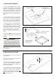
2. ASSESS ROOF STRENGTH - The roof members MUST be strong enough to support the weight of the unit (up to 50kg) without any roof deflection that will cause “pooling” of water around the unit. Contact your caravan manufacturer to confirm the max load the roof is able to handle. If in any doubt consider the use of an external “H” frame. DIRECTION OF TRAVEL LONGITUDINALS MUST BE FIXED SECURELY TO TRANSVERSE ROOF MEMBERS - If the roof does not have an existing hole one must be cut.
4. POSITION IBIS ON ROOF - Remove the air conditioner from the carton. - Position the unit over the gasket so that the corners of the square hole in the caravan roof line up with the corners of the square hole underneath the IBIS (Fig 6). TIP: Have one person inside the vehicle looking through the hole while the other is on the roof adjusting the position of the unit The unit weights approximately 50kg. Ensure a two person lift or use a mechanical hoist to avoid the risk of injury.
6. ASSESS ROOF THICKNESS Include ‘H’ frame if used Duct length required Hold down bolt length (mm) required (mm) 125 150 (as supplied) As supplied 100 125 (cut 25) As supplied 80 105 (cut 45) As supplied 60 85 (cut 65) Cut 50 40 65 (cut 85) Cut 70 25 (absolute minimum) 50 (cut 100) Cut 85 Roof thickness (mm) - Measure the roof thickness and consult the table across to check if adjustments to the hold down bolt and duct length are required.
8. ATTACH DUCT TO UNIT - Raise the brace assembly and slip the black plastic duct over the outside diameter of the outlet underneath the rooftop unit. Ensure that the notch cut in the plastic ductwork aligns with the fans power cable (Fig 12 & 13). When attaching the duct to the unit take care to ensure it forms a tight, unbroken seal that doesn’t allow cold air to escape. - Engage and tighten the four M8 bolts with the threaded inserts in the rooftop unit.
9. ATTACH PLENUM COVER - Secure the main plenum cover to the duct assembly with the 4 screws provided (Fig 16). TIP: It is important that these screws are not over tightened otherwise the plenum may crack. - Remove the filter elements by pulling them out of the plenum, and use the six self tapping counter sunk screws to secure the covers edges to the caravan ceiling (Fig 17). In some instances a very small pilot hole may need to be drilled to guide the screws into place.
COMMISSIONING OF THE UNIT 1. Turn the power on at the circuit breaker 2. Press the ON/OFF button and press the MODE button to select FAN 3. Cycle through the LO, MED and HIGH fan speeds checking that all speeds run. 4. Set mode to COOL, adjust temp via up/down buttons to say 4oC less than the display temp (I.e. Room temp) compressor will start within three minutes. 5. Set mode to HEAT, similarly set temp to say 4oC above display temp. Compressor will start within three minutes.
GENERAL SPECIFICATIONS Air – Conditioner Height Width Length Weight - 220mm 825mm 1040mm 44kg - 65mm 535mm 555mm 2.4kg Air Discharge Plenum Height Width Length Weight Electrical Rating: 240V, 50hz Nominal Cooling Capacity: 3.2 KW Nominal Heating Capacity: 3.4 KW Maximum Rated Current Cooling: 6A Maximum Rated Current Heating: 6.
OPERATING INSTRUCTIONS - Turn the unit on by pressing the ON/OFF button once. - Press the MODE button to cycle through options Cool, Dry, Heat and Fan. COOLING - Cycle mode button to highlight COOL. - You may select High, Med, Low or Auto fan speeds by pressing the fan button. It is recommenced that you choose Auto. - Now select the desired room temperature (herein referred to as SETPOINT) by pressing the TEMP up or down keys, the readout will flash the set point temperature.