Spring Haven READ AND SAVE ALL INSTRUCTIONS INSTRUCTION MANUAL WARRANTY CERTIFICATE
This product is protected by United States Federal and/or State Law, including Patent, Trademark and/or Copyright laws. Manual design and all elements of manual design are protected by U.S. Federal and/or State Law, including Patent, Trademark and/or Copyright laws. 1151 W.
WARRANTY The Aire warranty is for one (1) year from the date of purchase from an authorized Aire dealer. This warranty is only valid to the original purchaser or user against all defects in material and workmanship (light bulbs excluded) for one (1) full year. Additionally, Aire warrants the motor only for the lifetime of the Aire ceiling fan (excluding wall controls and electrical components), to the original purchaser or user. • The warranty is void with the use of any non-Aire electrical devices; e.g.
SAFETY RULES 1. To reduce the risk of electric shock, ensure electricity has been turned off at the circuit breaker or fuse box before beginning. 2. All wiring must be in accordance with the National Electrical Code “ANSI/NFPA 70-1999” and local electrical codes. Electrical installation should be performed by a qualified licensed electrician. 3. The outlet box and support structure must be securely mounted and capable of reliably supporting a minimum of 35 lbs.
PACKAGE CONTENTS Unpack your fan and check the contents. You should have the following items: 13. Receiver with 6 wire nuts 14. Transmitter+holder+2 mounting screws 15. 12V MN21/A23 battery A. Mounting hardware: #10 x 1.5" Wood screws (2 PCs.) #8 x 3/4" Machine screws (2 PCs.) Lock washers (2 PCs.) 4mm Star washers (2 PCs.) Wire nuts (3 PCs. ) Washers (2 PCs.) B. Blade attachment hardware: 3/16" x 17 mm Screws with lock washers (21 PCs.) C. Downrod Rubber Cover D. Balancing kit 1. Fan blades (5) 2.
INSTALLING THE FAN Tools Required: Phillips screw driver; slotted screw driver; step-ladder; wire cutters; electrical tape. MOUNTING OPTIONS If there isn't an existing mounting box, then read the following instructions. Disconnect the power by removing fuses or turning off circuit breakers. Secure the outlet box directly to the building structure. Use appropriate fasteners and building materials. The outlet box and its support must be able to fully support the moving weight of the fan (at least 50 lbs.).
HANGING THE FAN WARNING: All of the parts, hardware and components such as the hanger bracket and hanger ball have been provided for your safety and the proper installation of your new ceiling fan. The use of other parts, hardware or components not supplied by Aire with the fan will void the Aire Warranty. REMEMBER to turn off the power. Follow the steps below to hang your fan properly: Step 1. Secure the Hanger Bracket to the ceiling outlet box using the screws provided with your outlet box in conjunction.
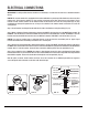
ELECTRICAL CONNECTIONS WARNING: To avoid possible electrical shock be sure electricity is turned off at the main fuse or breaker box before wiring. NOTE: This remote control unit is equipped with 16 code combinations to prevent possible interference from or to other remote units. The frequency switches on your receiver and remote control have been preset at the factory. Please recheck to make sure the switches on the remote control and the receiver are set to the same position (Fig. 11).
FINISHING THE INSTALLATION Step 1. Remove 1 of the 2 screws from the bottom of the hanger bracket and loosen the other one half a turn from the screw head. Step 2. Slide the canopy up towards the hanger bracket and place the key hole on the canopy over the screw on the hanger bracket, turn canopy until it locks in place at the narrow section of the key holes. (Fig. 14) Step 3. Align the circular hole on canopy with the remaining hole on the hanger bracket, secure by tightening the two set screws.
ATTACHING THE FAN BLADES Insert one fan blade into the blade slot on the motor housing and secure with the blade support plates and screws. Securely tighten screws. Repeat process with other blades. (Fig. 15) FAN BLADE SLOT FIG. 15 SCREWS BLADE SUPPORT PLATES INSTALLING THE MOUNTING PLATE Step 1. Remove 1 of 3 screws from the mounting ring and loosen the other 2 screws. (Do not remove) Step 2.
INSTALLING THE LIGHT KIT 1. Remove 1 of 3 screws from the light mounting plate and loosen the other 2 screws. (do not remove) 2. Raise and hold the light kit close to the light mounting plate and proceed to do the wire connections. Connect the white wire connectors from the light kit and fan, follow the same procedure with the black wire connector from the fan and the black wire connector from the light kit. (Fig. 17) 3.
INSTALLING THE LIGHT BULBS & GLASS SHADE WARNING: Shut off the power supply before removing or replacing lamp. In handling of halogen bulb, care should be taken not to touch it with your bare hands. Oil residue will shorten the life of the halogen bulb. If you accidentally come into contact, wipe thoroughly with a clean, lint-free, cotton cloth. Allow the bulb to cool for 10 minutes before changing the bulb. Use light bulb in accordance with the fan's specification. DO NOT EXCEED THE MAXIMUM WATTAGE RATING.
OPERATING THE REMOTE CONTROL Remote Control only: Install a A23 12 volt battery (included). (Fig. 19) To prevent damage to transmitter remove the battery if not used for long periods of time. Restore Power to Ceiling Fan. HI, MED, LOW buttons: Sets the fan speed. OFF button: Turns the fan off. button: Turns the light on or off and also controls the brightness setting. Press and release this button to turn the light on or off. Press and hold the button to set the desired brightness.
CARE OF YOUR FAN Here are some suggestions to help maintain your fan. 1. Because of the fan's natural movement some connections may become loose. Check the support connections, brackets and blade attachments twice a year. Make sure they are secure. (It is not necessary to remove fan from the ceiling). 2. Clean your fan periodically to help maintain its new appearance over the year. CAUTION: many common household cleaning products contain chemicals that could damage the finish of your fan.
TROUBLESHOOTING SYMPTOM SOLUTION Fan will not start Check to make sure the wall switch is turned on. Check circuit fuses or breakers. Caution! Make sure the power is turned off before performing the following steps. Remove canopy and check wire connections. Check wall control transmitter connections (if applicable). Note: Fan must be installed at a maximum distance of 40 feet from the transmitting unit for proper signal transmission between the transmitting unit and the fan's receiving unit.
SPECIFICATIONS Fan Size 52" Speed Volts Amps Watts RPM CFM Low 120 0.24 11.9 69 2176 Medium 120 0.41 34.0 122 4245 High 120 0.58 67.9 190 6105 N.W. G.W. C.F. 9.85 11.43 2.207' kgs kgs These are typical readings. Your actual fan may vary. They do not include amps and wattage used by the light(s). For any additional information about your Aire Ceiling fan, please write to: 1151 W.