
Manual


Chillers
ULTIMA COMPACT
Chillers
13
Technical Manual : Part No 6259543 TM E_1.3.0 04/2013
Design Features & Information
CONTROL SCHEME
FEATURES
Airedale recognises that all chiller applications are different but fall mainly into 2
application categories; Variable Supply Temperature and Constant Supply Temperature.
The onboard microprocessor has the capability of satisfying either control requirement as
illustrated below. Using the Airedale Variable Supply Temperature control scheme,
energy savings are available when compared with previous schemes and that of the
Constant Supply Temperature application.
Variable Supply Temperature control schemes offer energy savings where the supply
water temperature is not critical to its operation.
Selection of the best application control scheme can be made via a soft switch in the
microprocessor during initial commissioning.
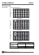
Examples based on Models UCC200D-6/2 having 6 Stages of Cooling
Variable Supply
Temperature Control
6
7
8
9
10
11
12
13
14
WATER TEMPERATURE °C
20%
40%
50%
60%
80%
100%
Chiller
Capacity %
Cooling Stage
Sequence
1
2
3
4
5
6
Return Water Temperature
Supply Water Temperature
Compressor Off
Mean Value
Constant Supply
Temperature Control
6
7
8
9
10
11
12
13
14
0
2
4
6
8
10
12
14
Supply Water Temperature
Return Water Temperature
Chiller
Capacity %
Cooling Stage
Sequence
20
40
50%
60
80
100%
1
2
3
4
5
6
WATER TEMPERATURE °C
CAUTION
Factory set to Variable Supply Temperature Control unless otherwise stated
at order.
Only when the mode selection has been set can the unit be enabled.