® AIRLESS PAINT Sprayer SERVICE/OPERATION MANUAL AIRLESSCO SL 6250 001-809 APR 09
TABLE OF CONTENTS SECTION Introduction...................................................... 1 Safety Warnings .............................................. 2 Setting Up........................................................ 5 Flushing ........................................................... 5 How to Flush ................................................... 6 Starting Up ...................................................... 7 Pressure Relief Procedure ..............................
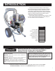
INTRODUCTION This gas powered airless sprayer is built tough to take the day after day high volume demands of painting contractors and equipment rental companies. The SL "Slow Stroker" paint pump features a large, severe duty, slow-stroking stainless steel piston. Airlessco's patented stationary triple-life packing system allows external adjusment of upper & lower packings. This SL6250 airless pumps are "Built to Perform...
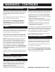
WARNINGS MEDICAL ALERT - Airless Spray Wounds If any fluid appears to penetrate your skin, get EMERGENCY MEDICAL CARE AT ONCE. DO NOT TREAT AS A SIMPLE CUT. Tell the doctor exactly what fluid was injected. Have him read the following "NOTE TO PHYSICIAN". WARNING HIGH PRESSURE SPRAY CAN CAUSE EXTREMELY SERIOUS INJURY. OBSERVE ALL WARNINGS. THIS SPRAYER IS FOR PROFESSIONAL USE ONLY.
WARNINGS - CONTINUED ALWAYS INSPECT SPRAYING AREA Keep clear of moving parts when starting or operating the sprayer. Do not put your fingers into any openings to avoid amputation by moving parts or burns on hot parts.Precaution is the best insurance against an accident. When starting the engine, maintain a safe distance from moving parts of the equipment.
WARNINGS - CONTINUED AVOID COMPONENT RUPTURE This sprayer operates at 3000 psi (205 bar). ALWAYS be sure that all components and accessories have a maximum working pressure of at least 3000 psi to avoid rupture which can result in serious bodily injury including injection and property damage. NEVER leave a pressurized sprayer unattended to avoid accidental operation of it which could result in serious bodily injury.
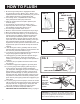
SETTING UP 1. CONNECT THE HOSE AND GUN a. Remove the plastic cap plug from the outlet and screw a conductive or grounded 3000 psi spray hose onto fluid outlet. b. Connect an airless spray gun to the other end of the hose, but do not install the spray tip yet! NOTE: Do not use thread sealer on swivel unions as they are made to self seal. NOTE: The first 50’ of hose should always be 3/8". 2. FILL THE PACKING NUT/WET CUP Fill the Packing Nut/Wet Cup 1/3 full with Airlessco Throat Seal Oil (TSO). FIG 1 BELOW.
HOW TO FLUSH 1. Be sure the gun safety latch is engaged and there is no spray tip in the gun. Refer to Fig. 2. Refer to your separate instruction manual provided with your gun on its safety features and how to engage safety latch. 2. Pour enough clean, compatible solvent into a large, empty metal pail to fill the pump and hoses. 3. Place the suction tube into the pail or place the pail under the pump. 4. Turn pressure control knob to low. Refer to Fig. 4. 5.
STARTING UP 1. LEARN THE CONTROLS PRESSURE CONTROL KNOB - used to adjust pressure only. Turn clockwise to increase pressure and counterclockwise to decrease pressure. (See Fig. 4) PRIME & PRESSURE RELIEF VALVE - Turn to OPEN position (see Fig. 3) to prime the pump. Turn to the CLOSED position to spray. FOLLOW "PRESSURE RELIEF PROCEDURES" ON PAGE 9 WHENEVER YOU: - are instructed to relieve pressure - stop spraying - checking or servicing any of the system equipment. - or installing or cleaning the spray tip.
STARTING UP CONTINUED 7. CLEANING A CLOGGED TIP a. Follow PRESSURE RELIEF PROCEDURE on page 9. b. Clean the front of the tip frequently (with toothbrush only) during the day to keep material from building up and clogging the tip. c. To clean and clear a tip if it clogs, refer to the separate instruction manual received with your gun and nozzle. IMPORTANT WARNING Always follow the PRESSURE RELIEF PROCEDURE on page 9 before perfoming any service or maintenance procedure.
PRESSURE RELIEF PROCEDURE ! IMPORTANT! TO AVOID POSSIBLE SERIOUS BODY INJURY, ALWAYS FOLLOW THIS PROCEDURE WHENEVER THE SPRAYER IS SHUT OFF, WHEN CHECKING IT, WHEN INSTALLING, CHANGING OR CLEANING TIPS, WHENEVER YOU STOP SPRAYING, OR WHEN YOU ARE INSTRUCTED TO RELIEVE THE PRESSURE. 1. Engage the gun safety latch. Refer to the separate instruction manual provided with your gun on its safety features and how to engage safety latch. 4.
AIRLESS SPRAY GUN OPERATION SPRAY Attach spray gun to airless unit and tighten fittings securely. Set the gun safety latch. (Also may be called gun safety lock, or trigger lock) FIG. 7 GUN SAFETY LATCH IN LOCKED POSITION GUN SAFETY LATCH * The gun safety latch should always be set when the gun is not being triggered. Read all warnings and safety precautions supplied with the spray gun and in product manual. RELEASED MAJOR COMPONENTS OF SPRAY GUN AND REVERSIBLE SPRAY TIP FIG.
AIRLESS SPRAY GUN FIG. 11 6 7 8 11* 10 9 5 4 12 1* 3* 2* 13 14 15 16 17 PARTS LIST FIGURE 5 Item No. Part No.
AIRLESS SPRAY TROUBLESHOOTING DEFECTS CAUSE CORRECTION Coarse spray Low pressure Increase the pressure Excessive fogging (overspray) High pressure Material too thin Reduce the pressure to satisfactory pattern distrabution Use less thinner Patten too wide Spray angle too large Use smaller spray angle tip Pattern too narrow Spray angle too small use larger spray angle tip ( if coverage is OK, try tip in same nozzle group) Too much material Nozzle too large Material too thin Pressure too high
TIP SELECTION GUIDE Spray tip selection is based on paint viscosity, paint type, & job needs. For light viscosities (thin paints), use a smaller tip; heavier (thicker paints), use a larger tip size. Spray tip size is based on how many gallons of paint per minute can be sprayed through the tip. Do not use a tip larger than maximum pump flow rate or capacity the sprayer can accommodate. Pump flow rate is measured in gallons per minute (GPM).
REGULAR MAINTENANCE 1. Always stop the pump at the bottom of its stroke when you take a break or at the end of the day. This helps keep material from drying on the rod, damaging the packings. 2. Keep the displacement pump packing nut/wet cup 1/3 full of Airlessco Throat Seal Oil at all times. The TSO helps protect the packings and rod. 3. Lubricate Connecting Rod Pin every 3 months. 4. Inspect the packing nut daily. Your paint pump has Airlessco's patented "Triple Life Packing System".
FIELD TROUBLESHOOTING PROBLEM CAUSE SOLUTION There is spitting from the gun. The fluid supply is low or empty. Air entrapped in the fluid pump or hose. Refill the supply container. Check for loose connections on the siphon assembly, tighten, then reprime pump. Paint leaks into the wet cup The packing nut/wet cup is loose. The upper packings are worn or damaged. Worn Piston Rod. Tighten just enough to stop leakage. Replace the packings. See pages 18-19.
SERVICING THE FLUID PUMP NOTE: CHECK EVERYTHING IN THE TROUBLESHOOTING CHART BEFORE DISASSEMBLING THE SPRAYER. FLUID PUMP REINSTALL FLUID PUMP DISCONNECT 1. Loosen the packing nut & extend piston rod to fully up position. See figure 14. 2. Insert one of the retaining rings through the packing nut and rest the sleeve on top of it. See figure 15 & 16. 3. Connect the connecting rod with the fluid pump by installing the coupling halves. Slide sleeve over the coupling halves and secure with retaining ring.
SERVICING INLET & OUTLET VALVES DISASSEMBLY OF THE OUTLET VALVE FIG. 19 1 1. Using the rod collar tool (189-211) , screw the suction nut, containing intake seat support, off of the fluid body. See Fig. 19. 2. Remove the inlet seat, O-ring, inlet ball and inlet retainer with O-ring. See Fig. 19. 3. Clean all parts and inspect them for wear or damage, replacing parts as needed. Old O-rings should be replaced with new ones. NOTE: INLET SEAT (187-065) IS REVERSIBLE. 4. Clean inside of fluid body. 5.
PACKING REPLACEMENT PROCEDURES DISASSEMBLY OF THE FLUID PUMP 1. Unscrew & remove the packing nut. 2. Push the piston rod down through the packings & out of the pump. 3. Now push the packing removal tool up through the pump & remove from the top bringing the packings, spacer & springs along with it, leaving the fluid body empty. *NOTE: MAKE SURE ALL PACKINGS & GLANDS HAVE BEEN REMOVED FROM THE FLUID PUMP. 4. Clean inside of fluid body. 5. Disassemble all parts & clean for reassembly.
PACKING REPLACEMENT PROCEDURES FIG. 21 FIG. 22 23 22 1 24 25 2 21 22 20 19 20 21 19 3 18 18 4 15 16 4 1 5 6 7 8 9 14 17 16 15 10 15 16 14 11 12 14 17 13 16 15 PARTS LIST FIGURE 21 & 22 Item No. 1 Part No. Description 187-330-99 Piston Rod PARTS LIST FIGURE 21 & 22 CONT Item No. Part No.
PAINT SYSTEM ASSEMBLY FIG. 23 9 10 11 12 SEE FIGURE 22 13 8 14 7 6 9 5 5 16 15 4 3 1 17 2 PARTS LIST FIGURE 23 Item No. Part No. 1 120-504 2 Item No. Part No.
PRIME VALVE (119-083) FIG. 24 1 2 3 4 PARTS LIST FIGURE 24 5 6 7 8 9 10 11 12 13 14 Item No. Part No. Description 1 115-303 Handle with Label 2 117-046 Screw 3 115-063 Washer 4 115-072 Spacer 5 115-064 Belleville Spring (3) 6 115-065 Retaining Ring 7 115-067 Washer 8 115-071 Valve Stem 9 115-068 O-Ring Black 10 115-069 Ball 11 115-029 Valve Seat 12 115-012 Washer 13 115-073 Valve Body 14 115-074 Inlet Fitting MANIFOLD FILTER (111-200-99) FIG.
REPLACEMENT OF ELECTRICAL CONTROL BOARD 1. Remove electrical cover. 2. Disconnect sensor lead from Electrical Board. 3. Disconnect two clutch leads on Electrical Board from leads on clutch. 4. Using a 1/16" allen, loosen set screw in Pressure Control Knob and remove knob. 5. Using a 1/2" nutdriver or 1/2" deep socket, remove nut from pressure control shaft. This will allow removal of electrical control board from frame. 6. Replace Electrical Board Assembly in reverse order.
ELECTRICAL TROUBLESHOOTING - Clutch Does Not Engage STEP 1: Ensure that the pressure control knob (POT) is in the maximum (CW) position. STEP 2: Remove the upper and lower clutch and electrical covers. STEP 3: Check all electrical connections between the engine magneto, sensor, control board and clutch for loose connections or damaged leads. See Fig.26. STEP 4: Disconnect the two leads from the control board (blue) and the clutch assembly (black).
CLUTCH REPLACEMENT INSPECTING THE CLUTCH 1. Inspect clutch and belt, replace as neccessary. INSTALLING THE CLUTCH REFER TO FIGURES 27-30 1. With gearbox held in a vice vertically as previously described, place first spacer, and bearing, onto gearbox shaft. See Fig. 28 2. Insert snap rings (2), into recesses of cog pulley portion of clutch. Place cog pulley portion of clutch with cog belt attached onto shaft. 3. Place second spacer, into cog pulley portion of clutch.
CLUTCH ASSEMBLY (301-284) FIG. 28 10 9 8 7 6 5 1 2 PARTS LIST FIGURE 28 4 3 1 Item No. Part No. 1 112-041 Differential Screw 2 112-054 Coupling Nut Assy 3 4 1/16” 2 Description 301-284-99 Replacement Clutch 301-037 Bearing (2) 5 301-274 Spacer (2) 6 100-333 Retaining Ring (2) 7 301-413 Removable Spacer 8 301-412 Spacer 9 136-068 Spring 10 301-316 Rubber Edge ENGINE ASSEMBLY FIG. 29 PARTS LIST FIGURE 29 1 2 3 4 5 6 7 8 9 Item No. Part No.
POWER UNIT ASSEMBLY (301-593) FIG. 30 1 2 FIGURE 26 8 3 4 9 FIGURE 23 10 11 7 6 40 5 12 13 35 32, 33, 34 39 38 37 3 14 31 36 17, 18 28, 29, 30 20, 21 FIGURE 22 FIGURE 32 27 26 25 PARTS LIST FIGURE 30 26 Item No. Part No. 1 301-320 2 3 Description 16 15 19 20, 21, 22, 23 21, 22, 23, 24 FIGURE 28 FIGURE 29 PARTS LIST FIGURE 30 CONT Item No. Part No.
FRAME ASSEMBLY (301-273) FIG. 31 12 11 2 1 10 3 4,5,6 7 8,9 PARTS LIST FIGURE 31 Item No. Part No. Description 1 301-201 Frame 2 301-202 Motor Bracket 3 301-165 Wheel (2) 4 136-126 Screw (4) 5 140-029 Washer (12) 6 100-317 Nut (4) 7 331-048 Rubber Boot (2) 8 305-039 Spacer (2) 9 143-029 Set Collar (2) 10 331-342 Screw (2) 11 100-270 Cup 12 120-021 Nut (2) SUCTION ASSEMBLY (301-594) FIG.
ACCESSORIES AIRLESSCO Quick Flush STAY CLEAN™ ™ Spray protectant for machine to prevent paint from sticking to it. Keeps your sprayer looking new for years! ■ The only clean water flushing system ■ Cuts sprayer clean-up time in half! ■ Connects to standard garden hose to backflush sprayer through gun 114-030 ■ Includes "F" and "G" adapters to work with all brands of gun 20 oz.
PROTECT YOUR EQUIPMENT INVESTMENT! MAIL THE CARD BELOW TO GET ALL THESE BENEFITS! WARRANTY VERIFICATION Prompt registration verifies your right to protection under the terms and conditions of your warranty. OWNER CONFIRMATION Completed warranty registration and purchase invoice copy serves as confirmation of ownership in the event of product loss by fire or theft.
AIRLESSCO LP, SL, and Surestripe Sprayers LIMITED WARRANTY AIRLESSCO warrants the LP, SL, and Surestripe series equipment manufactured by it and bearing it’s name to be free from defects in material and workmanship on the date of sale by an authorized Airlessco Distributor to the original purchaser. Airlessco will, for the period of twenty four months from the date of sale, repair or replace any part of the equipment proven defective. Packings and rods are limited to a 1-time replacement.