SkyIPCam500W Wireless Night Vision Network Camera Model # AICN500W User’s Manual Ver. 1.
Table of Content C H A P T E R 1 .................................................................................................................... 2 I N T R O D U C T I O N T O Y O U R C A M E R A .............................................................................. 2 1.1 Checking the Package Contents ........................................................................2 1.2 Getting to Know Your Camera............................................................................2 1.
C HAPTER 1 I NTRODUCTION TO Y OUR C AMERA 1.1 Checking the Package Contents Check the items contained in the package carefully. You should have the following: 5 5 5 5 5 5 5 One SkyIPCam500W Wireless Night Vision Network Camera. One Antenna. One AC Power Adapter. One Camera Stand. One Ethernet Cable (Cat.5). One Installation CD-ROM. One Quick Installation Guide. NOTE Once any item contained is damaged or missing, contact the store where you purchased the product. 1.
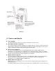
External Antenna Screw Hole is used to connect the camera stand. DC Power Connector is used to connect the power adapter, in order to supply power to the camera. Reset Button will restart the camera when it is pressed quickly; when it is long pressed for ten seconds, the camera will be reset to the factory’s default settings. Ethernet Cable Connector is used to connect the network cable, which supports the NWay protocol so that the camera can detect the network speed automatically. Rear View 1.
capture both still images and video clips, so that you can keep the archives and restore them at any time. 1.4 System Requirements Networking LAN: 10Base-T Ethernet or 100Base-TX Fast Ethernet. WLAN: 802.11b/g Wireless LAN Accessing the Camera using Web Browser Platform: Microsoft® Windows® 2000/XP/Vista CPU: Intel Pentium III 350MHz or above RAM: 128MB Resolution: 800x600 or above User Interface: Microsoft® Internet Explorer 6.
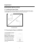
C HAPTER 2 H ARDWARE I NSTALLATION 2.1 Installing the Camera Stand The camera comes with a camera stand, which uses a swivel ball screw head to lock to the camera’s screw hole. When the camera stand is attached, you can place the camera anywhere by mounting the camera through the three screw holes located in the base of the camera stand. The Camera Stand 2.2 Connecting the Camera to LAN/WLAN Use the provided Ethernet cable to connect the camera to your local area network (LAN).
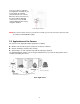
If you use a wireless network in your application environment, you need to attach the included external antenna to the camera. When the camera is powered on, the camera will automatically search any access point with “default” SSID and with security encryption disabled. Connecting the Antenna NOTE If the camera cannot connect to your wireless network, you need to connect the camera to LAN first and proceed with WLAN settings. 2.
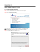
C HAPTER 3 S OFTWARE I NSTALLATION 3.1 Installing SkyIPCam Utility Step 1 Insert the provided CD and wait for the auto-run screen to appear. Step 2 Click on Install SkyIPCam Utility. Note: If the autorun screen does not appear automatically, go to Start, Run, type D:\ Utility\Setup.exe (where D is the letter of your CD drive) and click OK. Step 3 Keep clicking Next on the following screens.
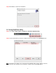
Step 4 Click Close to complete the installation. 3.2 Using SkyIPCam Utility Step 1 Go to Start > (All) Programs > Airlink101 > Airlink101 SkyIPCam Utiliy Step 2 Select the IP Camera you want to configure from the list and click on the Change IP button. Note: If the Camera’s IP address does not show up in the window, make sure the camera is properly connected to the same network as your computer is, and then click on the Search button.
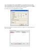
Step 3 You may simply accept the suggested Static IP, or you can manually change the last 3-digit number of the IP Address, in case that the suggested one has already been used by another device in the same network. Another option is that if your router’s DHCP server is enabled, you can select DCHP, so the router will automatically assign a dynamic IP address to your camera. Enter “admin” for both the ID and password, and click Change.
Step 5 A web browser window will open up requesting a username and password. Enter admin for both User name and Password, and click OK. Step 6 The camera viewing window will appear. Click on Setup, then click Smart Wizard. Step 7 Enter a name for your camera and a location if you like. Then enter “admin” for both Admin Password and Confirm Password. Click Next.
Step 8 You can change the camera’s IP settings in the below window. If you have done this in Step 3, click Next and go to the next step. Step 9 If you would like to set up email alerts that you can receive in the future, enter your email information here. You can get this information from your internet service provider. You can also set this up at a later time. Click Next.
Step 10 Enter the wireless information according to your wireless router’s (or access point’s) setting if you would like to connect the camera wirelessly to the network. You can log in to the router’s (or AP’s) web configuration pages to get the SSID and encryption details. Click Next. Step 11 Confirm your settings at the last window. If everything is correct, click Apply and the configuration is completed.
3.3 Viewing Images Method 1 --- Access from Web Browser Step 1 If you know the IP address of your network camera, you may open the Web Browser on your computer. Step 2 Type the IP address of your camera (the default IP is 192.168.1.240) in the Address bar, and then press [Enter]. Step 3 Enter “admin” for both the User name and Password, and click OK. Step 4 If it is the first time for your computer to access the Web based viewing page, you may be prompted to install the software of ActiveX Control.
Step 5 Click on Install, and then you may be able to view images. Step 6 To get a clear view of images, you can simply rotate the camera’s lens clockwise or counterclockwise to adjust the focus.
Method 2 --- Access from SkyIPCam Utility Step 1 Go to Start > (All) Programs > AirLink101 > AirLink101 SkyIPCam Utiliy, and open the Airlink101 SkyIPCam Utility.
Step 3 Follow Step 3 to Step 6 mentioned in Method 1.
3.4 Using SkyIPCam View To Install the Program Step 1 Click on Install SkyIPCam View from the auto-run screen.
To Launch the Program This section describes the user interface and operating instructions of SkyIPCam View. To launch the program, click Start > Programs > AirLink101 > AirLink101 SkyIPCam View, and the main screen will appear as below: NOTE Please set the resolution to 1024x768 or above on your computer while using SkyIPCam View; otherwise, the displayed main screen may be distorted.
Item Features The following describes the function of each item on the main screen: CONTROLS Panel - SETTING: Click to enter the Setting screen of SkyIPCam View. Click again to return to the main screen of SkyIPCam View. - PLAY: Click to play the recorded video file using the media player on the computer (for example, Windows Media Player by default). - LOCK: Click to lock the camera controls. Click again to resume controls for the camera.
CAMERA Panel - TRIGGER OUT: Click to turn on the trigger out connector of the camera. This button is available only when the connected camera supports the trigger out connector, which is used to control the external device connected to the camera, such as a light. - SNAPSHOT: Click to capture a still image using the selected camera and save the file in the computer. - RECORD: Click to start recording a video clip using the selected camera. Click again to stop recording and save the file in the computer.
- SWING: If you have saved two or more positions for the selected camera, click this button to control the camera swinging from one position to another position. Video View Window and Camera List Video View Window Camera List - Video View Window: This window displays the video view of the selected camera, which can be divided into 4/9/16 windows according to your selection in VIEW SELECTION panel. - Camera List: This list displays the information of the connected camera(s). To Add a Camera 1.
3. In the pop-up Add New Camera dialog window, you can: z Select the Search tab if you are not sure of the camera’s IP address. Click Search camera to search the available camera within the network. Once the camera is found and is shown in the list, select it and click Add Camera. z Select the Input tab to add a camera by entering its IP address directly. Enter the camera’s IP address (default: 192.168.1.240) and Port (default: 80), and then click Add Camera. 4.
To Remove a Camera 1. Click SETTING in the CONTROLS panel to display the Setting screen. 2. Select a camera from the list and click Delete Camera. Select a camera To Link to the Web Page of the Camera Click SETTING > Camera List > Camera Configuration and then Link web page to launch the Web browser that displays live view image and Web Configuration of the selected camera.
When the motion detection function of the selected camera is enabled, you can configure the camera to start recording triggered by the motion detected. Click SETTING > Motion Configuration, and then select the Recording option to enable the selected camera to record by motion detection. z Schedule recording This recording method will work after you have completed the required settings in Schedule Recording Configuration. The recording schedule can be defined by Schedule Period or Recording Time.
- Recording Time: First, select the camera from the pull-down list and select Recording time tab. Then, select the weekday from the day buttons and then set the time period. Click Apply to save the settings. To Configure the Recording Settings To configure the recording settings, including the storage folder and storage options, click SETTING > Recording Configuration.
To Playback the Recorded Video The recorded video clips are saved in your computer, and can be played using the media player on the computer, such as Windows Media Player. To start playback, simply click the PLAY button on the CONTROLS panel, and the following dialog screen will appear, allowing you to select the file to playback. Select the recorded video file under the [camera] path and then click Open to launch the media player to playback.
To Set up Motion Detection Options When the motion detection function of the selected camera is enabled, you can set the Motion Options by selecting Alarm, Recording, Send e-Mail, and Trigger Out under SETTING > Motion Configuration. z Alarm: Select Beep or Music to alert you for the motion detected. When you select Music, you can customize the sound by clicking Browse and then selecting your favorite music (*.wav or *.mp3 file) in the computer.
- Mail From: Enter the email address of the user who will send the email. For example, John@mymail.com. - Mail To: Enter the email address of the user who will receive the email. - User Name: Enter the user name to login the mail server. - Password: Enter the password to login the mail server. - Subject: Enter a subject for the notification email. Account You can set a username and password for the camera here.
Other Allows you to set the rotation interval if monitoring multiple cameras.
Information Click SETTING > About to display the information of the software application.
C HAPTER 4 C ONFIGURATION 4.1 Using the Web Configuration You can access and manage the camera through the Web browser and the provided software application SkyIPCam View. This chapter describes the Web Configuration, and guides you through the configuration of the camera by using the web browser. To configure the camera, click Setup on the main page of Web Configuration. The Web Configuration will start from the Basic page. 4.
Basic >> Date & Time Date & Time - TimeZone: Select the proper time zone for the region from the pull-down menu. - Synchronize with PC: Select this option and the date & time settings of the camera will be synchronized with the connected computer. - Synchronize with NTP Server: Select this option and the time will be synchronized with the NTP Server. You need to enter the IP address of the server and select the update interval in the following two boxes.
When you are finished, click Add/Modify to add the new user to the camera. To modify the user’s information, select the one you want to modify from UserList and click Add/Modify. - UserList: Display the existing users of the camera. To delete a user, select the one you want to delete and click Delete. Guest - User Name: Enter the guest’s name you want to add to use the camera. - Password: Enter the password for the new guest. - UserList: Display the existing guests of the camera.
Network >> Network IP Setting This item allows you to select the IP address mode and set up the related configuration. - DHCP: Select this option when your network uses the DHCP server. When the camera starts up, it will be assigned an IP address from the DHCP server automatically. It is recommended that you NOT use DCHP. You should instead use Static IP mode to set a static IP so that the IP address will never change and you will always know what it is.
- HTTP Port: The default HTTP port is 80. Some ISP’s have port 80 blocked. If you are having problems, you can change it to some other port. The suggested port to be used is anything between 1024 to 65535 Network >> IP Filter The IP Filter setting allows the administrator of the camera to limit the users within a certain range of IP addresses to access the camera.
Image Setting - Brightness: Adjust the brightness level from 0 ~ 100. - Contrast: Adjust the contrast level from 0 ~ 100. - Saturation: Adjust the colors level from 0 ~ 100. Click Default to restore the default settings of the three options above. - Mirror: Select the Horizontal option to mirror the image horizontally. Select the Vertical option to mirror the image vertically. - Light Frequency: Select the proper frequency according to the camera’s location: 50Hz, 60Hz, or Outdoor.
Video & Audio >> Video MJPEG - Video Resolution: Select the desired video resolution from the three formats: VGA, QVGA and QQVGA. The higher setting (VGA) obtains better video quality while it uses more resource within your network. QQVGA is the lowest video quality setting but it provides the best speed over the network. - Video Quality: Select the desired image quality from five levels: Lowest, Low, Normal, High, and Highest.
4.5 Event Server Configuration The Event Server menu contains two sub-menus that allow you to upload images to FTP, and send emails that include still images. When you complete the required settings for FTP, or Email, click Test to find out if the related configuration is correct or not. Once the camera connects to the server successfully, click Apply. Event Server Setting>> FTP FTP - Host Address: Enter the IP address of the target FTP server.
Email - SMTP Server Address: Enter the mail server address. For example, mymail.com. - Sender Email Address: Enter the email address of the user who will send the email. For example, John@mymail.com. - Sender User Name: Enter the user name to login the mail server. - Sender Password: Enter the password to login the mail server. - Receiver #1 Email Address: Enter the first email address of the user who will receive the email.
4.7 Event Configuration The Event Configuration menu contains four sub-menus that provide the commands to configure event profiles. Event Configuration >> General Setting - Snapshot/Recording Subfolder: You can assign a given sub-folder for captured file. Otherwise, leave this option blank to use the default setting. Event Configuration >> Schedule Profile This sub-menu displays the scheduled profile(s).
- Time List: Display the time period that you have assigned within the selected weekday. To assign the same time period to every weekday, click Add this to all weekdays; click Delete this from all weekdays to remove the selected time period from every weekday. Click Delete to remove the selected time period. - Start/End Time: Enter the start and end time and then click Add to assign a time period within in the selected weekday.
You can separately configure the schedule for trigger function of the camera by Email, or FTP. Select the Enable option on each item, and then select a Schedule Profile from the pull-down list and set the Interval time. 4.8 Tools The Tools menu provides the commands that allow you to restart or reset the camera. You can also backup and restore your configuration, and upgrade the firmware for the camera. Factory Reset Click Reset to restore all factory default settings for the camera.
4.9 Information The Information menu displays the current configuration and events log of the camera. Device Info Display the Basic, Video & Audio, and Network settings of the camera. System Log The Logs table displays the events log recorded by the system.
C HAPTER 5 A PPENDIX A.1 Specification Image Sensor Sensor Resolution 1/4” color CMOS 640x480 Video Compression Video resolution MJPEG VGA/QVGA/QQVGA; 30fps max.
EMI FCC Class B, CE Class B A.2 Glossary of Terms NUMBERS 10BASE-T 100BASE-TX 10BASE-T is Ethernet over UTP Category III, IV, or V unshielded twisted-pair media. The two-pair twisted-media implementation of 100BASE-T is called 100BASE-TX. A ADPCM AMR Applet ASCII ARP AVI Adaptive Differential Pulse Code Modulation, a new technology improved from PCM, which encodes analog sounds to digital form.
E Enterprise network Ethernet An enterprise network consists of collections of networks connected to each other over a geographically dispersed area. The enterprise network serves the needs of a widely distributed company and operates the company’s mission-critical applications. The most popular LAN communication technology. There are a variety of types of Ethernet, including 10Mbps (traditional Ethernet), 100Mbps (Fast Ethernet), and 1,000Mbps (Gigabit Ethernet).
monthly cost for a direct connection. J JAVA Java is a programming language that is specially designed for writing programs that can be safely downloaded to your computer through the Internet without the fear of viruses. It is an object-oriented multi-thread programming best for creating applets and applications for the Internet, Intranet and other complex, distributed network. L LAN Local Area Network a computer network that spans a relatively small area sharing common resources.
network operating system are the Internetwork Packet Exchange (IPX) protocol or the Internet Protocol (IP). Protocols that dictate the format of data for transferors the medium include token-passing and Carrier Sense Multiple Access with Collision Detection (CSMA/CD), implemented as token-ring, ARCNET, FDDI, or Ethernet.
WAN WEP Windows WPA WPA2 Wide-Area Network. A wide-area network consists of groups of interconnected computers that are separated by a wide distance and communicate with each other via common carrier telecommunication techniques. WEP is widely used as the basic security protocol in Wi-Fi networks, which secures data transmissions using 64-bit or 128-bit encryption. Windows is a graphical user interface for workstations that use DOS.
1 Technical Support E-mail: support@airlink101.com Toll Free: 1-888-746-3238 Web Site: www.airlink101.com *Theoretical maximum wireless signal rate based on IEEE standard 802.11g specifications. Actual data throughput will vary. Network conditions and environmental factors, including volume of network traffic, building materials and construction, mix of wireless products used, radio frequency interference (e.g.
- 51 -