Wireless G 2.4GHz 500mW Outdoor AP Model: APO1000/APO1010 User’s Manual V.1.
Table of Contents CHAPTER 1. SYSTEM OVERVIEW............................................................................................................................. 1 1.1 INTRODUCTION ........................................................................................................................................................ 1 1.2 SYSTEM CONCEPT ..................................................................................................................................................
4.3.5 Backup / Restore and Reset to Factory .................................................................................................. 69 4.3.6 Firmware Upgrade...................................................................................................................................... 70 4.3.7 Network Utility ............................................................................................................................................. 71 4.3.8 Reboot...........................
6.4.6 Firmware Upgrade.................................................................................................................................... 140 6.4.7 Network Utility ........................................................................................................................................... 141 6.4.8 Reboot........................................................................................................................................................ 142 6.
4
Chapter 1. System Overview 1.1 Introduction The 802.11 b/g compliant Airlink101® APO1000/APO1010 is an outdoor wireless access point that can be used for five different purposes in three different modes. In the AP mode, it can be deployed either as traditional fixed wireless Access Point(AP), or combination of AP and WDS(AP+WDS). In the WDS mode, it’s only used to expand or bridge Ethernet networks and deployed as a main base, relay based or remote base station.
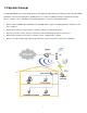
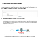
1.2 System Concept The APO1000/APO1010 is not only designed and used as traditional outdoor AP, but also with rich features tailored for WISP applications. The two-level management capability and access control ease WISP and owners to maintain and manage wireless network in a more controllable fashion. Main applications are listed as follows with illustration: 1. Wireless CPE for Multi Dwelling Unit/Multi Tenant Unit (MDU/MTU) complexes including apartments, dormitories, and office complexes. 2.
1.3 Applications in Wireless Network APO1000/APO1010 is a multiple mode system which can be configured either as a wireless gateway or an access point as desired. It also can be used as WDS link for Ethernet network expansion. This section depicts different applications in AP Mode, WDS Mode, and CPE Mode and Client Bridge + Universal Repeater Mode. Configuration in AP Mode (including Access Point + WDS) An access point can be either a main, relay or remote base station.
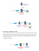
APO1000/APO1010 APO1000/APO1010 Configuration in WDS Mode (Pure WDS) An access point can be either a main, relay or remote base station. A main base station is typically connected to a wired network via the Ethernet port. A relay base station relays data between main base stations and relay stations or remote base stations with clients. A remote base station is the end point to accept connections from wireless clients and pass data upwards to a network wirelessly.
APO1000/APO1010 5
Î Example 2 : Point-to-Multi-Point APO1000/APO1010 Î Example 3 : Multi-Point Repeating bridge APO1000/APO1010 Configuration in CPE Mode It can be used as an Outdoor Customer Premises Equipment (CPE) to receive wireless signal over last mile application, helping WISPs deliver wireless broadband Internet service to residents and business customers. In the CPE mode, APO1000/APO1010 is a gateway enabled with NAT and DHCP Server functions.
Configuration in Client Bridge + Universal Repeater Mode It can be used as an Client Bridge + Universal Repeater to receive wireless signal over last mile applications, helping WISPs deliver wireless broadband Internet service to new residential and business customers. In this mode, APO1000/APO1010 is enabled with DHCP Server functions. The wired clients of APO1000/APO1010 are in the same subnet from Main Base Station and it accepts wireless connections from client devices.
1.4 Product Benefit 500mW at 2.
1.5 Specification Wireless Architecture Mode Î AP Mode 9 9 Pure AP Mode • It can be deployed as a tradition fixed wireless Access Point • It allow wireless clients or Stations(STA ) to access AP/WDS Mode • This enables the wireless interconnection of Access Point in an IEEE802.11 network .and accept wireless clients at the same time Î WDS Mode 9 This enables the wireless interconnection of Access Point in an IEEE802.11 network.
7. Î Support MAC Filter Î Support IP Filter Î Bandwidth traffic Shaping Wireless Feature Î Transmission power control : 9 Levels Î Channel selection : Manual or Auto Î No of associated clients per AP : 32 Î Setting for max no associated clients : Yes Î No. of ESSID (Virtual AP) : 8 Î No. of Max. WDS setting : 8 Î Preamble setting : Short/ Long Î Setting for 802.11b/g mix, 802.11b only or 802.
Î No. of registered RADIUS servers : 2 Î VLAN assignment on BSSID Î Support VLAN tag over WDS Quality of Service Î DiffServ/ ToS Î IEEE802.1p/ CoS Î IEEE 802.1Q Tag VLAN priority control Î IEEE802.
Chapter 2. Basic Installation 2.1 Hardware Installation 2.1.1 Package Contents The standard package contents of APO1000/APO1010: APO1000/APO1010 x1 Quick Installation Guide x1 CD-ROM (with User Manual and QIG) x1 PSE with AC Cable x1 Mounting Kit x1 It is highly recommended to use all the supplies in the package instead of substituting any components by other suppliers to guarantee best performance.
2.1.2 Panel Function Descriptions ¾ APO1000 Front Panel 1. Reset Button : Rear Panel System reboot button press until LED flashed and release for system reboot or for reset to factory default press, LED flashes keep pressing until LED becomes static 2. Power : Red LED ON indicates power on, and OFF indicates power off 3. Signal Strength : Yellow LED ON indicates Low Signal (CPE Mode) 4. Signal Strength : Green LED ON indicates Normal Signal (CPE Mode) or (WDS Mode only) 5.
¾ APO1010 Front Panel 1. Reset Button : Rear Panel System reboot button press until LED flashed and release for system reboot or for reset to factory default press, LED flashes keep pressing until LED becomes static 2. Power : Red LED ON indicates power on, and OFF indicates power off 3. Signal Strength : Yellow LED ON indicates Low Signal (CPE Mode) 4. Signal Strength : Green LED ON indicates Normal Signal (CPE Mode) or (WDS Mode only) 5.
2.1.3 Hardware Installation Steps Please follow the steps mentioned below to install the hardware of APO1000/APO1010: ¾ APO1000 Front Panel Rear Panel Î Connect N-type antenna to the N-type connector on the rear panel. Î Connect Power Injector to the PoE connector on the front panel. Î Connect an Ethernet cable to the Power Injector and the other end to a computer. Î Source power to Power Injector in order to supply power to APO1000.
2.2 Web Management Interface Instructions APO1000/APO1010 supports web-based configuration. Upon the completion of hardware installation, APO1000/APO1010 can be configured through a COMPUTER by using its web browser such as Internet Explorer or Mozilla Firefox. 1. Default IP Address : 192.168.2.254 2. Default IP Netmask : 255.255.255.0 3.
The network manager Login Page then appears. Enter “root” for user name and “default” for password, and then click OK to login to the system; the root manager account is used as an example here. Login Success System Overview page will appear after successful login.
Chapter 3. AP Mode Configuration When AP mode is chosen, the system can be configured as an Access Point. This section provides detailed explanation for users to configure in the AP mode with help of illustrations. In the AP mode, functions listed in the table below are also available from the Web-based GUI interface.
3.1.2 Configure LAN IP Here are the instructions to setup the local IP Address and Netmask. Please click on System -> LAN and follow the below setting. Mode : Check either “Static IP” or “Dynamic IP” button as desired to set up the system IP of LAN port . Î Î Static IP : The administrator can manually setup the LAN IP address when static IP is preferred. 9 IP Address : The IP address of the LAN port; default IP address is 192.168.1.
APO1000/APO1010 APO1000/APO1010 Click Save button to save your changes.
3.2 Wireless LAN Network Creation The network manager can configure related wireless settings, General Settings, Advanced Settings, Virtual AP(VAP) Setting, Security Settings, and MAC Filter Settings. 3.2.1 Wireless General Setup The administrator can change the data transmission, channel and output power settings for the system. Please click on Wireless -> General Setup and follow the below setting. MAC address : The MAC address of the Wireless interface is displayed here.
3.2.2 Wireless Advanced Setup To achieve optimal wireless performance, it is necessary to tweak advance setting per requirements properly, not necessary higher the better or lower. The administrator can change the RTS threshold and fragmentation threshold settings for the system. Please click on Wireless -> Advanced Setup and follow the below setting. Slot Time : Slot time is in the range of 1~1489 and set in unit of microsecond. The default value is 20 microsecond.
performance the ACK Timeout could be made longer to accommodate. RTS/CTS Adjustment of RTS Threshold can be done to turn on RTS. CTS Timeout will take effect only when RTS is turned on. Unlike wired Ethernet, radio transmission may begin with a RTS (Request to Send) frame, and receiver responds with a CTS (Clear to Send) frame. The RTS/CTS mechanism is called Channel Cleaning, all stations that received CTS will back off for certain period of time, multiple of the slot time.
DTIM Interval : The DTIM interval is in the range of 1~15. The default is 15. DTIM is defined as Delivery Traffic Indication Message. It is used to notify the wireless stations, which support power saving mode, when to wake up to receive multicast frame. DTIM is necessary and critical in wireless environment as a mechanism to fulfill power-saving synchronization. A DTIM interval is a count of the number of beacon frames that must occur before the access point sends the buffered multicast frames.
3.2.3 Create Virtual AP(VAP) The APO1000/APO1010 support broadcasting multiple SSIDs, allowing the creation of Virtual Access Points, partitioning a single physical access point into 8 logical access points, each of which can have a different set of security, VLAN tag(ID) and network settings. Figure 3-2 shows multiple SSIDs with different security type and VLAN settings. APO1000/APO1010 Figure 3-2 Multiple SSIDs with different Security Type and VLAN Tag 3.2.3.
3.2.3.2 Virtual AP Setup For each Virtual AP, administrators can configure SSID, VLAN ID(Tag), SSID broadcasting, Maximum number of client associations, security type settings. Click Edit button on the VAP Edit column, and then a Virtual AP setup page appears. ESSID : Extended Service Set ID, When clients are browsing for available wireless networks, this is the SSID that will appear in the list. ESSID will determine the service type available to AP clients associated with the specified VAP.
AC_VO Voice 0x30 0xe0 0x88 0xb8 6, 7 High Time-sensitive data like VoIP and streaming media are automatically sent to this queue IAPP Support : By default, it’s “Disable”. Inter Access-Point Protocol is designed to enforce unique association throughout an ESS(Extended Service Set) and to enforce secure exchange of station's security context between current access point (AP) and new AP during hand off period. IAPP supported only for WPA-PSK/WPA2-PSK, WPA-Enterprise/WPA2-Enterprise and 802.
Î Key Length Hex ASCII 64-bit 10 characters 5 characters 128-bit 26 characters 13 characters 152-bit 32 characters 16 characters WPA-PSK/WPA2-PSK : WPA or WPA2 Algorithms enable the system to access the network by using the WPA-PSK protected access. 9 Cipher Suite : By default, it is TKIP. Select either AES or TKIP cipher suites 9 Group Key Update Period : By default, it is 600 seconds. This time interval for rekeying GTK, broadcast/multicast encryption keys, in seconds.
key to generate GTKs, in seconds. Enter the time-length required. • 9 9 EAP Reauth Period :; By default, it’s 3600 seconds; 0 second is to disable EAP Re-authentication. Main and secondary Authentication RADIUS Server Settings : • Authentication Server : Enter the IP address of the Authentication RADIUS server. • Port : By default, it’s 1812. The port number used to communicate with RADIUS server. • Shared secret : A secret key used between system and RADIUS server. Supports 1 to 64 characters.
RADIUS settings to complete configuration. 9 Dynamic WEP Settings : • W E P Key length : The available options are 64 bits or 128 bits. The system will automatically generate WEP encryption keys. 9 9 • WEP Key Update Period : By default, it’s 300 seconds; 0 not to rekey. • EAP Reauth Period : By default, it’s 3600 seconds; 0 second is to disable EAP Re-authentication.
• Accounting Server : Enter the IP address of the Accounting RADIUS server. • Port : By default, it’s 1813. The port number used to communicate with RADIUS server. • Shared Secret : A secret key used between system and Accounting RADIUS server. Supports 1 to 64 characters. Click Save button to save your changes.
3.2.4 MAC Filter Setup Continued from the 3.2.3.1 Virtual AP Overview section, Click Setup button on the MAC Filter Setup column, and then a Virtual AP MAC Filter setup page appears. The administrator can allow or reject clients to access each Virtual AP. MAC Filter Setup : By default, it’s “Disable”. Options are Disabled, Only Deny List MAC or Only Allow List MAC. Click Save button to save your change. Two ways to set the MAC filter rules : Î Only Allow List MAC.
3.3 Wireless Network Expansion The administrator could create WDS Links to expand wireless network. When WDS is enabled, access point functions as a wireless bridge and is able to communicate with other access points via WDS links. A WDS link is bidirectional and both side must support WDS. Access points know each other by MAC Address. In other words, each access point needs to include MAC address of its peer. Ensure all access points are configured with the same channel and own same security type settings.
WMM prioritizes traffic according to four Access Categories (AC) - voice, video, best effort, and background. However, it does not provide guaranteed throughput. Packets with QoS header including Diffserv/IP ToS and 802.1p will be mapped into 4 Access Categories of WMM, packets without QoS header will be assigned to the Best Effort queue. Please refer to the table below for mapping from 802.1p and ToS mapping to WMM: Queue Data Transmitted Clients to AP IP ToS 802.1P Priority AC_BK Background.
Key Length Hex ASCII 64-bit 10 characters 5 characters 128-bit 26 characters 13 characters 152-bit 32 characters 16 characters Î AES Key : Enter 32 HEX characters AES key. WDS MAC List Î Enable : Click Enable to create WDS link. Î WDS Peer's MAC Address : Enter the MAC address of WDS peer. Î VLAN ID : By default, it’s disabled(space) with no VLAN ID. When desired, this system supports tagged VLAN from 0 to 4094. Î Description : Description of WDS link.
3.4 System Management 3.4.1 Configure Management Administrator could specify geographical location of the system via instructions in this page. Administrator could also enter new Root and Admin passwords and allow multiple login methods. Please click System -> Management and follow the below settings. System Information Î System Name : Enter a desired name or use the default one. Î Description : Provide description of the system. Î Location : Enter geographical location information of the system.
Admin Login Methods : Only root user can enable or disable system login methods and change services port. Î Enable HTTP : Check to select HTTP Service. Î HTTP Port : The default is 80 and the range is between 1 ~ 65535. Î Enable Telnet : Check to select Telnet Service Î Telnet Port : The default is 23 and the range is between 1 ~ 65535. Click Save button to save your changes.
3.4.2 Configure System Time System time can be configured via this page, and manual setting or via a NTP server is supported. Please click on System -> Time Server and follow the below setting. Local Time : Display the current system time. NTP Client : To synchronize the system time with NTP server. Î Enable : Check to select NTP client. Î Default NTP Server : Select the NTP Server from the drop-down list. Î Time Zone : Select a desired time zone from the drop-down list.
3.4.3 Configure UPnP Universal Plug and Play(UPnP) is an architecture to enable pervasive peer-to-peer network connectivity between PCs, intelligent devices and appliances when UPnP is supported. UPnP works on TCP/IP network to enable UPnP devices to connect and access to each other, very well adopted in home networking environment. UPnP : By default, it’s “Disable”. Select “Enable” or “Disable” of UPnP Service.
3.4.4 Configure SNMP Setup SNMP is an application-layer protocol that provides a message format for communication between SNMP manager and agent. By enabling SNMP function, the administrator can obtain the system information remotely. Please click on System -> SNMP Setup and follow the below setting. SNMP v2c Enable: Check to enable SNMP v2c. Î ro community : Set a community string to authorize read-only access. Î rw community : Set a community string to authorize read/write access.
SNMP Trap : Events such as cold start, interface up & down, and association & disassociation will report to an assigned server. Î Community : Set a community string required by the remote host computer that will receive trap messages or notices send by the system. Î IP : Enter the IP addresses of the remote hosts to receive trap messages. Click Save button to save changes and click Reboot button to activate.
3.4.5 Backup / Restore and Reset to Factory Backup current configuration, restore prior configuration or reset back to factory default configuration can be executed via this page. Please click on Utilities -> Profile Setting and follow the below setting. Save Settings To PC : Click Save button to save the current configuration to a local disk. Load Settings from PC : Click Browse button to locate a configuration file to restore, and then click Upload button to upload.
3.4.6 Firmware Upgrade Firmware is the main software image that system needs to respond to requests and to manage real time operations. Firmware upgrades are sometimes required to include new features or bugs fix. It takes around 8 minutes to upgrade due to complexity of firmware. To upgrade system firmware, click Browse button to locate the new firmware, and then click Upgrade button to upgrade. 1. 2.
3.4.7 Network Utility The administrator can diagnose network connectivity via the PING utility. Please click on Utilities -> Network Utility and follow the below setting. Ping : This utility will help ping other devices on the network to verify connectivity. Ping utility, using ICMP packets, detects connectivity and latency between two network nodes. As result of that, packet loss and latency time are available in the Result field while running the PING test.
3.4.8 Reboot This function allows user to restart system with existing or most current settings when changes are made. Click Reboot button to proceed and take around three minutes to complete. A reminder will be available for remaining time to complete. If power cycle is necessary, please wait till completion of the reboot process. The System Overview page appears upon the completion of reboot.
3.5 System Status This section breaks down into subsections of System Overview, Associated Clients Status, WDS Link Status, Extra Information and Event Log. 3.5.1 System Overview Display detailed information of System, Network, LAN and Wireless in the System Overview page. System : Display information of the system. Î System Name : The name of the system. Î Operating Mode : The mode currently in service. Î Location : Deployed geographical location. Î Description : A description of the system.
Î Primary DNS : The primary DNS server in service. Î Secondary DNS : The secondary DNS server in service. LAN Information : Display total received and transmitted statistics on the LAN interface. Î MAC Address : The MAC address of the LAN port. Î Receive bytes : The total received packets in bytes on the LAN port. Î Receive packets : The total received packets of the LAN port. Î Transmit bytes : The total transmitted packets in bytes of the LAN port.
3.5.2 Associated Clients Status It displays ESSID, on/off Status, Security Type, total number of wireless clients associated with all Virtual AP. VAP Information : Highlights key VAP information. Î VAP : Available VAP from VAP0 to VAP7. Î ESSID : Display name of ESSID for each VAP. Î Status : On/Off Î Security Type : Display chosen security type; WEP, WPA/WPA2-PSK, WPA/WPA2-Enterprise. Î Clients : Display total number of wireless connections for each VAP.
3.5.3 WDS Link Status On/Off Status, peers MAC Address, Received Signal Strength Indicator (RSSI) and Last TX Time for each WDS are available. WDS : Maximum supported WDS links. Status : On/Off. MAC Address : Display MAC address of WDS peer. RSSI : Indicate the RSSI of WDS links. Last TX Time : Last inactive time period in seconds on WDS links. If display “0” RSSI, you need to check WDS configuration. Things to verify are MAC Address, Channel and Security type.
3.5.4 Extra Information Users could pull out information such as Route table, ARP table, MAC table, Bridge table or STP available in the drop-down list from system. The “Refresh” button is used to retrieve latest table information. Route table information : Select “Route table information” on the drop-down list to display route table. APO1000/APO1010 could be used as a L2 or L3 device. It doesn’t support dynamic routing protocols such as RIP or OSPF.
Ageing timers will be reset when existing MAC addresses in table are learned again or added when new MAC addresses are seen from wired or wireless interfaces as well. When time runs out for a particular entry, it will be pruned from the table. In that situation, switching packet to that particular MAC address will be dropped. Bridge STP Information : Select “Bridge STP Information” on the drop-down list to display a list of bridge STP information.
3.5.5 Event Log The Event log displays system events when system is up and running. Also, it becomes very useful as a troubleshooting tool when issues are experienced in system. Time: The date and time when the event occurred. Facility: It helps users to identify source of events such “System” or “User” Severity: Severity level that a specific event is associated such as “info”, “error”, “warning”, etc. Message: Description of the event.
Chapter 4. WDS Mode Configuration Please refer to illustrations of the section 1.3 for possible applications in the WDS mode. This section provides detailed explanation for users to configure in the WDS mode with help of illustrations. In the WDS mode, functions listed in the table below are also available from the Web-based GUI interface.
4.1.2 Configure LAN IP Here are the instructions for how to setup the local IP Address and Netmask. Please click on System -> LAN and follow the below setting. Î Mode : Check either “Static IP” or “Dynamic IP” button as desired to set up the system IP of LAN port . Î Static IP : The administrator can manually setup the LAN IP address when static IP is available/ preferred. Î 9 IP Address : The IP address of the LAN port; default IP address is 192.168.10.
APO1000/APO1010 APO1000/APO1010 Click Save button to save your changes.
4.2 Wireless Network Expansion The network manager can configure related wireless settings, General Settings, Advanced Settings, Virtual AP Setting and Security Settings. 4.2.1 Wireless General Setup The administrator can change the data transmission, channel and output power settings for the system. Please click on Wireless -> General Setup and follow the below setting. MAC address : The MAC address of the Wireless interface is displayed here.
4.2.2 Wireless Advanced Setup To achieve optimal wireless performance, it is necessary to tweak advance setting per requirements properly, not necessary higher the better or lower. The administrator can change the RTS threshold and fragmentation threshold settings for the system. Please click on Wireless -> Advanced Setup and follow the below setting. Slot Time : Slot time is in the range of 1~1489 and set in unit of microsecond. The default value is 20 microsecond.
performance the ACK Timeout could be made longer to accommodate. RTS/CTS Adjustment of RTS Threshold can be done to turn on RTS. CTS Timeout will take effect only when RTS is turned on. Unlike wired Ethernet, radio transmission may begin with a RTS (Request to Send) frame, and receiver responds with a CTS (Clear to Send) frame. The RTS/CTS mechanism is called Channel Cleaning, all stations that received CTS will back off for certain period of time, multiple of the slot time.
DTIM Interval : The DTIM interval is in the range of 1~15. The default is 15. DTIM is defined as Delivery Traffic Indication Message. It is used to notify the wireless stations, which support power saving mode, when to wake up to receive multicast frame. DTIM is necessary and critical in wireless environment as a mechanism to fulfill power-saving synchronization. A DTIM interval is a count of the number of beacon frames that must occur before the access point sends the buffered multicast frames.
4.2.3 WDS Setup The administrator could create WDS Links to expand wireless network. When WDS is enabled, access point functions as a wireless bridge and is able to communicate with other access points via WDS links. A WDS link is bidirectional and both side must support WDS. Access points know each other by MAC Address. In other words, each access point needs to include MAC address of its peer. Ensure all access points are configured with the same channel and own same security type settings.
WMM prioritizes traffic according to four Access Categories (AC) - voice, video, best effort, and background. However, it does not provide guaranteed throughput. Packets with QoS header including Diffserv/IP ToS and 802.1p will be mapped into 4 Access Categories of WMM, packets without QoS header will be assigned to the Best Effort queue. Please refer to the table below for mapping from 802.1p and ToS mapping to WMM: Queue Data Transmitted Clients to AP IP ToS 802.1P Priority AC_BK Background.
WDS MAC List Î Enable : Click Enable to create WDS link. Î WDS Peer's MAC Address : Enter the MAC address of WDS peer. Î VLAN ID : By default, it’s disabled(space) with no VLAN ID. When desired, this system supports tagged VLAN from 0 to 4094. Î Description : Description of WDS link. The WDS link needs to be set at same Channel and Security Type. Click Save button to save your changes.
4.3 System Management 4.3.1 Configure Management Administrator could specify geographical location of the system via instructions in this page. Administrator could also enter new Root and Admin passwords and allow multiple login methods. Please click System -> Management and follow the below settings. System Information Î System Name : Enter a desired name or use the default one. Î Description : Provide description of the system. Î Location : Enter geographical location information of the system.
Admin Login Methods : Only root user can enable or disable system login methods and change services port. Î Enable HTTP : Check to select HTTP Service. Î HTTP Port : The default is 80 and the range is between 1 ~ 65535. Î Enable HTTPS : Check to select HTTPS Service Î HTTPS Port : The default is 443 and the range is between 1 ~ 65535. If you already have an SSL Certificate, please click “UploadKey” button to select the file and upload it.
4.3.2 Configure System Time System time can be configured via this page, and manual setting or via a NTP server is supported. Please click on System -> Time Server and follow the below setting. Local Time : Display the current system time. NTP Client : To synchronize the system time with NTP server. Î Enable : Check to select NTP client. Î Default NTP Server : Select the NTP Server from the drop-down list. Î Time Zone : Select a desired time zone from the drop-down list.
4.3.3 Configure UPnP Universal Plug and Play(UPnP) is an architecture to enable pervasive peer-to-peer network connectivity between PCs, intelligent devices and appliances when UPnP is supported. UPnP works on TCP/IP network to enable UPnP devices to connect and access to each other, very well adopted in home networking environment. UPnP : By default, it’s “Disable”. Select “Enable” or “Disable” of UPnP Service.
4.3.4 Configure SNMP Setup SNMP is an application-layer protocol that provides a message format for communication between SNMP managers and agents. By enabling SNMP function, the administrator can obtain the system information remotely. Please click on System -> SNMP Setup and follow the below setting. SNMP v2c Enable : Check to enable SNMP v2c. Î ro community : Set a community string to authorize read-only access. Î rw community : Set a community string to authorize read/write access.
Î Community : Set a community string required by the remote host computer that will receive trap messages or notices send by the system. Î IP : Enter the IP addresses of the remote hosts to receive trap messages. Click Save button to save changes and click Reboot button to activate.
4.3.5 Backup / Restore and Reset to Factory Backup current configuration, restore prior configuration or reset back to factory default configuration can be executed via this page. Please click on Utilities -> Profile Setting and follow the below setting. Save Settings to PC : Click Save button to save the current configuration to a local disk. Load Settings from PC : Click Browse button to locate a configuration file to restore, and then click Upload button to upload.
4.3.6 Firmware Upgrade Firmware is the main software image that system needs to respond to requests and to manage real time operations. Firmware upgrades are sometimes required to include new features or bugs fix. It takes around 8 minutes to upgrade due to complexity of firmware. To upgrade system firmware, click Browse button to locate the new firmware, and then click Upgrade button to upgrade. 1. 2. To prevent data loss during firmware upgrade, please back up current settings before proceeding.
4.3.7 Network Utility The administrator can diagnose network connectivity via the PING utility. Please click on Utilities -> Network Utility and follow the below setting. Ping : This utility will help ping other devices on the network to verify connectivity. Ping utility, using ICMP packets, detects connectivity and latency between two network nodes. As result of that, packet loss and latency time are available in the Result field while running the PING test.
4.3.8 Reboot This function allows user to restart system with existing or most current settings when changes are made. Click Reboot button to proceed and take around three minutes to complete. A reminder will be available for remaining time to complete. If power cycle is necessary, please wait till completion of the reboot process. The System Overview page appears upon the completion of reboot.
4.4 System Status This section breaks down into subsections of System Overview, WDS Link Status, Extra Information and Event Log. 4.4.1 System Overview Detailed information on System, Network, LAN Information and Wireless Information can be reviewed via this page. System : Display the information of the system. Î System Name : The name of the system. Î Operating Mode : The mode currently in service. Î Location : The reminding note on the geographical location of the system.
LAN Information : Display total received and transmitted statistics on the LAN interface. Î MAC Address : The MAC address of the LAN port. Î Receive bytes : The total received packets in bytes on the LAN port. Î Receive packets : The total received packets of the LAN port. Î Transmit bytes : The total transmitted packets in bytes of the LAN port. Î Transmit packets : The total transmitted packets of the LAN port.
4.4.2 WDS Link Status On/Off Status, peers MAC Address, Received Signal Strength Indicator(RSSI) and Last TX Time for each WDS are available. WDS : Maximum supported WDS links. Status : On/Off. MAC Address : Display MAC address of WDS peer. RSSI : Indicate the RSSI of WDS links. Last TX Time : Last inactive time period in seconds on WDS links. If display “0” RSSI, you need to check WDS configuration. Things to verify are MAC Address, Channel and Security type.
4.4.3 Extra Information Users could pull out information such as Route table, ARP table, MAC table, Bridge table or STP available in the drop-down list from system. The “Refresh” button is used to retrieve latest table information. Route table information : Select “Route table information” on the drop-down list to display route table. APO1000/APO1010 could be used as a L2 or L3 device. It doesn’t support dynamic routing protocols such as RIP or OSPF.
Ageing timers will be reset when existing MAC addresses in table are learned again or added when new MAC addresses are seen from wired or wireless interfaces as well. When time runs out for a particular entry, it will be pruned from the table. In that situation, switching packet to that particular MAC address will be discontinued. Bridge STP Information : Select “Bridge STP Information” on the drop-down list to display a list of bridge STP information.
4.4.4 Event Log The Event log displays system events when system is up and running. Also, it becomes very useful as troubleshooting tool when issues are experienced in system. Time: The date and time when the event occurred. Facility: It helps users to identify source of events such “System” or “User” Severity: Severity level that a specific event is associated such as “info”, “error”, “warning”, etc. Message: Description of the event.
Chapter 5. CPE Mode Configuration When CPE mode is chosen, the system can be configured as a Customer Premises Equipment(CPE). This section provides detailed explanation for users to configure in the CPE mode with help of illustrations. In the CPE mode, functions listed in the table below are also available from the Web-based GUI interface.
APO1000/APO1010 Figure 5-1 CPE mode configuration 80
5.1.2 Configure WAN Setup There are three connection types for the WAN port : Static IP, Dynamic IP and PPPoE. Please click on System -> WAN and follow the below setting. In CPE mode, the WAN Port is the Wireless interface. Î Mode : By default, it’s “Static IP”. Check “Static IP”, “Dynamic IP” or “PPPoE” to set up system WAN IP. Î Static IP : Users can manually setup the WAN IP address with a static IP provided by WISP. Î 9 IP Address : The IP address of the WAN port.
Î User Name : Enter User Name for PPPoE connection Î Password : Enter Password for PPPoE connection Î Reconnect Mode : 9 Always on – A connection to Internet is always maintained. 9 On Demand – A connection to Internet is made as needed. When Time Server is enabled at the “On Demand” mode, the “Reconnect Mode” will turn out “Always on”. 9 Manual – Click the “Connect” button on “WAN Information” in the Overview page to connect to the Internet.
The Clone MAC Address field will display MAC address of the PC connected to system. Click “Save” button can make clone MAC effective. Î Manual MAC Address : Enter the MAC address registered with your ISP. Bandwidth : Administrator can control download and upload bandwidth. Default is Disable Î Upload : The range is from 256 to 8192 in Kbits Î Download : The range is from 256 to 8192 in Kbits Click Save button to save your changes.
5.1.3 Configure DDNS Setup Dynamic DNS allows you to map domain name to dynamic IP address. Please click on System -> DDNS Setup and follow the below setting. Enabled: By default, it’s “Disable”. The mapping domain name won’t change when dynamic IP changes. The beauty of it is no need to remember the dynamic WAP IP while accessing to it.
5.1.4 Configure LAN IP Here are the instructions for how to setup the local IP Address and Netmask. Please click on System -> LAN and follow the below setting. LAN IP : The administrator can manually setup the LAN IP address. Î IP Address : The IP address of the LAN port; default IP address is 192.168.10.100 Î IP Netmask : The Subnet mask of the LAN port; default Netmask is 255.255.255.0 Î 802.
Î DNS2 IP : Enter IP address of the second DNS server; this is optional. Î WINS IP : Enter IP address of the Windows Internet Name Service (WINS) server; this is optional. Î Domain : Enter the domain name for this network. Î Lease Time : The IP addresses given out by the DHCP server will only be valid for the duration specified by the lease time. Increasing the time ensure client operation without interruptions, but could introduce potential conflicts.
5.2 Access Point Association 5.2.1 Wireless General Setup The administrator can change the data transmission, channel and output power settings for the system. Please click on Wireless -> General Setup and follow the below setting. ESSID : Assign Service Set ID for the wireless system. Band Mode : Select an appropriate wireless band; bands available are 801.11b, 802.11g and 802.11b+802.11g.
key. The WEP key configured here must be exactly the same as the key on the access point that this system is associated with.
9 Key Length : The available options are 64 bits, 128 bits or 152 bits. 9 WEP auth Method : Enable the desired option among Open system and Shared. 9 Key Index : key index is used to designate the WEP key during data transmission. 4 different WEP keys can be entered at the same time, but only one is chosen. 9 WEP Key # : Enter HEX or ASCII format WEP key value; the system supports up to 4 sets of WEP keys.
5.2.2 Wireless Advanced Setup To achieve optimal wireless performance, it is necessary to tweak advance setting per requirements properly, not necessary higher the better or lower. The administrator can change the RTS threshold and fragmentation threshold settings for the system. Please click on Wireless -> Advanced Setup and follow the below setting. Slot Time : Slot time is in the range of 1~1489 and set in unit of microsecond. The default value is 20 microsecond.
performance the ACK Timeout could be made longer to accommodate. RTS/CTS Adjustment of RTS Threshold can be done to turn on RTS. CTS Timeout will take effect only when RTS is turned on. Unlike wired Ethernet, radio transmission may begin with a RTS (Request to Send) frame, and receiver responds with a CTS (Clear to Send) frame. The RTS/CTS mechanism is called Channel Cleaning, all stations that received CTS will back off for certain period of time, multiple of the slot time.
Select “Enable”, then packets with WMM QoS will take higher priority. WMM prioritizes traffic according to four Access Categories (AC) - voice, video, best effort, and background. However, it does not provide guaranteed throughput. Packets with QoS header including Diffserv/IP ToS and 802.1p will be mapped into 4 Access Categories of WMM, packets without QoS header will be assigned to the Best Effort queue. Please refer to the table below for mapping from 802.
5.2.3 Site Survey Use this tool to scan and locate WISP Access Points and select one to associate with. Please click on Wireless -> Site Survey. Below depicts an example for site survey. ESSID : Available Extend Service Set ID of surrounding Access Points. MAC Address : MAC addresses of surrounding Access Points. Channel : Channel numbers used by all found Access Points. Signal Level : Received signal strength of all found Access Points.
5.3 System Management 5.3.1 Configure Management Administrator could specify geographical location of the system via instructions in this page. Administrator could also enter new Root and Admin passwords and allow multiple login methods. Please click System -> Management and follow the below settings. System Information Î System Name : Enter a desired name or use the default one. Î Description : Provide description of the system. Î Location : Enter geographical location information of the system.
Admin Login Methods : Only root user can enable or disable system login methods and change services port. Î Enable HTTP : Check to select HTTP Service. Î HTTP Port : The default is 80 and the range is between 1 ~ 65535. Î Enable HTTPS : Check to select HTTPS Service Î HTTPS Port : The default is 443 and the range is between 1 ~ 65535. If you already have an SSL Certificate, please click “UploadKey” button to select the file and upload it.
5.3.2 Configure System Time System time can be configured via this page, and manual setting or via a NTP server is supported. Please click on System -> Time Server and follow the below setting. Local Time : Display the current system time. NTP Client : To synchronize the system time with NTP server. Î Enable : Check to select NTP client. Î Default NTP Server : Select the NTP Server from the drop-down list. Î Time Zone : Select a desired time zone from the drop-down list.
5.3.3 Configure UPnP Universal Plug and Play(UPnP) is an architecture to enable pervasive peer-to-peer network connectivity between PCs, intelligent devices and appliances when UPnP is supported. UPnP works on TCP/IP network to enable UPnP devices to connect and access to each other, very well adopted in home networking environment. UPnP : By default, it’s “Disable”. Select “Enable” or “Disable” of UPnP Service.
5.3.4 Configure SNMP Setup SNMP is an application-layer protocol that provides a message format for communication between SNMP managers and agents. By enabling SNMP function, the administrator can obtain the system information remotely. Please click on System -> SNMP Setup and follow the below setting. SNMP v2c Enable: Check to enable SNMP v2c. Î ro community : Set a community string to authorize read-only access. Î rw community : Set a community string to authorize read/write access.
SNMP Trap : Events such as cold start, interface up & down, and association & disassociation will report to an assigned server. Î Community : Set a community string required by the remote host computer that will receive trap messages or notices send by the system. Î IP : Enter the IP addresses of the remote hosts to receive trap messages. Click Save button to save changes and click Reboot button to activate.
5.3.5 Backup / Restore and Reset to Factory Backup current configuration, restore prior configuration or reset back to factory default configuration can be executed via this page. Please click on Utilities -> Profile Setting and follow the below setting. Save Settings to PC : Click Save button to save the current configuration to a local disk. Load Settings from PC : Click Browse button to locate a configuration file to restore, and then click Upload button to upload.
5.3.6 Firmware Upgrade Firmware is the main software image that system needs to respond to requests and to manage real time operations. Firmware upgrades are sometimes required to include new features or bugs fix. It takes around 8 minutes to upgrade due to complexity of firmware. To upgrade system firmware, click Browse button to locate the new firmware, and then click Upgrade button to upgrade. 1. 2. To prevent data loss during firmware upgrade, please back up current settings before proceeding.
5.3.7 Network Utility The administrator can diagnose network connectivity via the PING utility. Please click on Utilities -> Network Utility and follow the below setting. Ping : This utility will help ping other devices on the network to verify connectivity. Ping utility, using ICMP packets, detects connectivity and latency between two network nodes. As result of that, packet loss and latency time are available in the Result field while running the PING test.
5.3.8 Reboot This function allows user to restart system with existing or most current settings when changes are made. Click Reboot button to proceed and take around three minutes to complete. A reminder will be available for remaining time to complete. If power cycle is necessary, please wait till completion of the reboot process. The System Overview page appears upon the completion of reboot.
5.4 Access Control List 5.4.1 IP Filter Setup Allows to create deny or allow rules to filter ingress or egress packets from specific source and/or to destination IP address on wired (LAN) or Wireless (WAN) ports. Filter rules could be used to filter unicast or multicast packets on different protocols as shown in the IP Filter Setup. Important to note that IP filter rules has precedence over Virtual server rules. Please click on Advance -> IP Filter Setup and follow the below setting.
¾ Example 1 : Create a higher priority rule to allow IP address 192.168.2.2 Telnet access from LAN port first, and deny Telnet access from remaining IP addresses in the same subnet. Rule Source IP/Mask ¾ Destination Port IP/Mask Port In/Out Protocol Listen Action Side 1 192.168.2.2/32 192.2.254/32 22 In TCP n Pass LAN 2 192.168.2.0/24 192.168.2.254/32 22 In TCP n Deny LAN Example 2 : All Telnet access to the system from the IP addresses of subnet 192.168.2.
5.4.2 MAC Filter Setup Allows to create MAC filter rules to allow or deny unicast or multicast packets from limited number of MAC addresses. Important to note that MAC filter rules have precedence over IP Filter rules. Please click on Advance -> MAC Filter Setup and follow the below setting. MAC Filter Rule : By default, it’s “Disable”. Options are Disabled, Only Deny List MAC or Only Allow List MAC. Click Save button to save your change. Two ways to set the Access Control List: Î Only Allow List MAC.
5.5 Resource Sharing 5.5.1 DMZ DMZ is commonly work with the NAT functionality as an alternative of Virtual Server(Port Forwarding) while wanting all ports of DMZ host visible to Internet users. Virtual Server rules have precedence over the DMZ rule. In order to use a range of ports available to access to different internal hosts Virtual Server rules are needed. Please click on Advance -> DMZ and follow the below setting. DMZ : By default, it’s “Disable”. Check Enable radial button to enable DMZ.
5.5.2 Virtual Server (Port Forwarding) “Virtual Server” can also referred to as “Port Forward” as well and used interchangeably. Resources in the network can be exposed to the Internet users in a controlled manner including on-line gaming, video conferencing or others via Virtual Server setup. Don’t repeat ports’ usage to avoid confusion. Please click on Advance -> Virtual Server and follow the below setting. Virtual Server : By Default, It’s “Disable”.
¾ Example 2 : All connections should be redirected to 192.168.2.12 while DMZ is enabled. Since Virtual Server rules have precedence over the DMZ rule all other connections to TCP port 20~80 will be redirected to port 20~80 of 192.168.2.11. The rule 2 won’t take effect. DMZ Enabled : 192.168.2.12 Rule Protocol Private IP Private Port Public Port 1 TCP 192.168.2.11 20:80 20:80 2 TCP 192.168.2.
5.6 System Status This section breaks down into subsections of System Overview, DHCP Clients, Extra Information and Event Log. 5.6.1 System Overview Detailed information on System, WAN Information, LAN Information and Wireless Station Information can be reviewed via this page. System : Display the information of the system. Î System Name : The name of the system. Î Operating Mode : The mode currently in service. Î Location : The reminding note on the geographical location of the system.
The WAN port specified Dynamic IP, the Release and Renew button will be show-up, click Release button to release IP address of WAN port, Renew button to renew IP address through DHCP server. The WAN port specified PPPoE, and the Connect and DisConnect button will be show up. Click “Connect” button to assigned IP address from PPPoE server, “DisConnect” button to release IP address of WAN port. Î Mode : Supports Static, Dynamic, and PPPoE modes.
If the system associate with AP, the BSSID, RSSI and Last Rx Time will be show up. Below depicts the examples for associated AP of Wireless Information. Î BSSID : Indicate the Basic Service Set ID of the associated AP Î RSSI : Indicate the RSSI of the associated AP. Î Last Rx Time : Indicate the last receive packet of the associated AP LAN Information : Display total received and transmitted statistics on the LAN interface. Î MAC Address : The MAC address of the LAN port.
5.6.2 DHCP Clients Users could retrieve DHCP server and DHCP clients’ IP/MAC address via this page. IP address : IP addresses to LAN devices by DHCP server. MAC Address : MAC addresses of LAN devices. Expired In : Shows how long the leased IP address will expire.
5.6.3 Extra Info Users could pull out information such as Route table, ARP table, MAC table, Bridge table or STP available in the drop-down list from system. The “Refresh” button is used to retrieve latest table information. Netstat Information : Select “NetStatus Information” on the drop-down list, the connection track list should show-up, the list can be updated using the Refresh button.
Bridge table information : Select “Bridge Table information” on the drop-down list to display bridge table. Bridge table will show Bridge ID and STP's Status on the each Ethernet bridge and its attached interfaces, the Bridge Port should be attached to some interfaces. Bridge MAC information : Select “Bridge MACs Information” on the drop-down list to display MAC table.
5.6.4 Event Log The Event log displays system events when system is up and running. Also, it becomes very useful as troubleshooting tool when issues are experienced in system. Time: The date and time when the event occurred. Facility: It helps users to identify source of events such “System” or “User” Severity: Severity level that a specific event is associated such as “info”, “error”, “warning”, etc. Message: Description of the event.
Chapter 6. Client Bridge + Universal Repeater Configuration When Client Bridge + Universal Repeater mode is activated, the system can be configured as an Access Point and Client Station simultaneously. This section provides information in configuring the Client Bridge + Universal Repeater mode with graphical illustrations. APO1000/APO1010 provides functions as stated below where they can be configured via a userfriendly web based interface.
6.1.2 Configure LAN IP Here are the instructions for how to setup the local IP Address and Netmask. Please click on System -> LAN and follow the below setting. Mode : Check either “Static IP” or “Dynamic IP” button as desired to set up the system IP of LAN port . Î Static IP : The administrator can manually setup the LAN IP address when static IP is available/ preferred. 9 IP Address : The IP address of the LAN port; default IP address is 192.168.2.
802.1d Spanning Tree The spanning tree network protocol provides a loop free topology for a bridged LAN between LAN interface. The Spanning Tree Protocol, which is also referred to as STP, is defined in the IEEE Standard 802.1d. DHCP Setup : Devices connected to the system can obtain an IP address automatically when this service is enabled. Î DHCP : Check Enable button to activate this function or Disable to deactivate this service.
6.2 Access Point Association 6.2.1 Configure Wireless General Setting The administrator can change the data transmission, channel and output power settings for the system. Please click on Wireless -> General Setup and follow the below setting. ESSID : Assign Service Set ID for the wireless system. Band Mode : Select an appropriate wireless band; bands available are 801.11b, 802.11g and 802.11b+802.11g.
9 Key Length : The available options are 64 bits, 128 bits or 152 bits. 9 WEP auth Method : Enable the desired option among Open system and Shared. 9 Key Index : key index is used to designate the WEP key during data transmission. 4 different WEP keys can be entered at the same time, but only one is chosen. 9 WEP Key # : Enter HEX or ASCII format WEP key value; the system supports up to 4 sets of WEP keys.
6.2.2 Wireless Advanced Setup To achieve optimal wireless performance, it is necessary to tweak advance setting per requirements properly, not necessary higher the better or lower. The administrator can change the RTS threshold and fragmentation threshold settings for the system. Please click on Wireless -> Advanced Setup and follow the below setting. Slot Time : Slot time is in the range of 1~1489 and set in unit of microsecond. The default value is 20 microsecond.
RTS/CTS Adjustment of RTS Threshold can be done to turn on RTS. CTS Timeout will take effect only when RTS is turned on. Unlike wired Ethernet, radio transmission may begin with a RTS (Request to Send) frame, and receiver responds with a CTS (Clear to Send) frame. The RTS/CTS mechanism is called Channel Cleaning, all stations that received CTS will back off for certain period of time, multiple of the slot time.
saving mode, when to wake up to receive multicast frame. DTIM is necessary and critical in wireless environment as a mechanism to fulfill power-saving synchronization. A DTIM interval is a count of the number of beacon frames that must occur before the access point sends the buffered multicast frames. For instance, if DTIM Interval is set to 3, then the Wi-Fi clients will expect to receive a multicast frame after receiving three Beacon frame.
6.2.3 Site Survey Use this tool to scan and locate WISP Access Points and select one to associate with. Please click on Wireless -> Site Survey. Below depicts an example for site survey. ESSID : Available Extend Service Set ID of surrounding Access Points. MAC Address : MAC addresses of surrounding Access Points. Channel : Channel numbers used by all found Access Points. Signal Level : Received signal strength of all found Access Points.
6.3 Wireless LAN Network Creation The network manager can configure related wireless settings, AP Setup, Security Settings, and MAC Filter Settings. 6.3.1 AP Setup Administrators can configure ESSID, SSID broadcasting, Maximum number of client associations, security type settings and MAC Filter settings. ESSID : Extended Service Set ID, When clients are browsing for available wireless networks, this is the SSID that will appear in the list.
Queue Data Transmitted Clients to AP IP ToS 802.1P Priority AC_BK Background. 0x08 0x20 1, 2 AC_BE Best Effort AC_VI Video 0x28 0xa0 4, 5 High Minimum delay. Time-sensitive video data is automatically sent to this queue Voice 0x30 0xe0 0x88 0xb8 6, 7 High Time-sensitive data like VoIP and streaming media are automatically sent to this queue AC_VO 0, 3 Priority Description High throughput.
Î WPA-PSK/WPA2-PSK : WPA or WPA2 Algorithms enable the system to access the network by using the WPA-PSK protected access. 9 Cipher Suite : By default, it is TKIP. Select either AES or TKIP cipher suites 9 Group Key Update Period : By default, it is 600 seconds. This time interval for rekeying GTK, broadcast/multicast encryption keys, in seconds. Entering the time-length is required. 9 Master Key Update Period : By default, it is 83400 seconds.
9 9 Main and secondary Authentication RADIUS Server Settings : • Authentication Server : Enter the IP address of the Authentication RADIUS server. • Port : By default, it’s 1812. The port number used to communicate with RADIUS server. • Shared secret : A secret key used between system and RADIUS server. Supports 1 to 64 characters. • Accounting Server : Enable or Disable accounting features in RADIUS server.
Î WEP 802.1X : When WEP 802.1x Authentication is enabled, please refer to the following Dynamic WEP and RADIUS settings to complete configuration. 9 Dynamic WEP Settings : • WEP Key length : The available options are 64 bits or 128 bits. The system will automatically generate WEP encryption keys. 9 • WEP Key Update Period : By default, it’s 300 seconds; 0 not to rekey. • EAP Reauth Period : By default, it’s 3600 seconds; 0 second is to disable EAP Re-authentication.
9 Main and secondary Accounting RADIUS Server Settings : • Accounting Server : Enter the IP address of the Accounting RADIUS server. • Port : By default, it’s 1813. The port number used to communicate with RADIUS server. • Shared Secret : A secret key used between system and Accounting RADIUS server. Supports 1 to 64 characters. Click Save button to save your changes.
6.3.2 MAC Filter Setup The administrator can allow or reject clients to access repeater AP. Please click Wireless -> MAC Filter and follow the below settings. MAC Filter Setup : By default, it’s “Disable”. Options are Disabled, Only Deny List MAC or Only Allow List MAC. Click Save button to save your change. Two ways to set the MAC filter rules : Î Only Allow List MAC. The wireless clients in the MAC Filter List will be allowed to access to Access Point; All others will be denied.
6.4 System Management 6.4.1 Configure Management Administrator could specify geographical location of the system via instructions in this page. Administrator could also enter new Root and Admin passwords and allow multiple login methods. Please click System -> Management and follow the below settings. System Information Î System Name : Enter a desired name or use the default one. Î Description : Provide description of the system. Î Location : Enter geographical location information of the system.
Admin Login Methods : Only root user can enable or disable system login methods and change services port. Î Enable HTTP : Check to select HTTP Service. Î HTTP Port : The default is 80 and the range is between 1 ~ 65535. Î Enable HTTPS : Check to select HTTPS Service Î HTTPS Port : The default is 443 and the range is between 1 ~ 65535. If you already have an SSL Certificate, please click “UploadKey” button to select the file and upload it.
6.4.2 Configure System Time System time can be configured via this page, and manual setting or via a NTP server is supported. Please click on System -> Time Server and follow the below setting. Local Time : Display the current system time. NTP Client : To synchronize the system time with NTP server. Î Enable : Check to select NTP client. Î Default NTP Server : Select the NTP Server from the drop-down list. Î Time Zone : Select a desired time zone from the drop-down list.
6.4.3 Configure UPnP Universal Plug and Play(UPnP) is an architecture to enable pervasive peer-to-peer network connectivity between PCs, intelligent devices and appliances when UPnP is supported. UPnP works on TCP/IP network to enable UPnP devices to connect and access to each other, very well adopted in home networking environment. UPnP : By default, it’s “Disable”. Select “Enable” or “Disable” of UPnP Service.
6.4.4 Configure SNMP Setup SNMP is an application-layer protocol that provides a message format for communication between SNMP manager and agent. By enabling SNMP function, the administrator can obtain the system information remotely. Please click on System -> SNMP Setup and follow the below setting. SNMP v2c Enable: Check to enable SNMP v2c. Î ro community : Set a community string to authorize read-only access. Î rw community : Set a community string to authorize read/write access.
SNMP Trap : Events such as cold start, interface up & down, and association & disassociation will report to an assigned server. Î Community : Set a community string required by the remote host computer that will receive trap messages or notices send by the system. Î IP : Enter the IP addresses of the remote hosts to receive trap messages. Click Save button to save changes and click Reboot button to activate.
6.4.5 Backup / Restore and Reset to Factory Backup current configuration, restore prior configuration or reset back to factory default configuration can be executed via this page. Please click on Utilities -> Profile Setting and follow the below setting. Save Settings To PC : Click Save button to save the current configuration to a local disk. Load Settings from PC : Click Browse button to locate a configuration file to restore, and then click Upload button to upload.
6.4.6 Firmware Upgrade Firmware is the main software image that system needs to respond to requests and to manage real time operations. Firmware upgrades are sometimes required to include new features or bugs fix. It takes around 8 minutes to upgrade due to complexity of firmware. To upgrade system firmware, click Browse button to locate the new firmware, and then click Upgrade button to upgrade. 1. 2.
6.4.7 Network Utility The administrator can diagnose network connectivity via the PING utility. Please click on Utilities -> Network Utility and follow the below setting. Ping : This utility will help ping other devices on the network to verify connectivity. Ping utility, using ICMP packets, detects connectivity and latency between two network nodes. As result of that, packet loss and latency time are available in the Result field while running the PING test.
6.4.8 Reboot This function allows user to restart system with existing or most current settings when changes are made. Click Reboot button to proceed and take around three minutes to complete. A reminder will be available for remaining time to complete. If power cycle is necessary, please wait till completion of the reboot process. The System Overview page appears upon the completion of reboot.
6.5 System Status This section breaks down into subsections of System Overview, Associated Clients Status, DHCP Client List, Extra Information and Event Log. 6.5.1 System Overview Display detailed information of System, Network, LAN and Wireless in the System Overview page. System : Display the information of the system. Î System Name : The name of the system. Î Operating Mode : The mode currently in service. Î Location : The reminding note on the geographical location of the system.
Î IP Netmask : The network mask. By default, it’s 255.255.255.0. Î IP Gateway : The gateway IP address and by default, it’s 192.168.2.1. Î Primary DNS : The primary DNS server in service. Î Secondary DNS : The secondary DNS server in service. LAN Information : Display the detailed receive and transmit statistics of LAN interface. Î MAC Address : The MAC address of the LAN port. Î Receive bytes : The total received packets in bytes on the LAN port.
Î BSSID : Indicate the Basic Service Set ID of the associated AP. Î RSSI : Indicate the RSSI of the associated AP. Î Last Rx Time : Indicate the last receive packet of the associated AP. Î MAC Address : The MAC address of the Wireless Station port. Î Receive bytes : The total received packets in bytes on the Wireless Station port. Î Receive packets : The total received packets on the Wireless Station port.
6.5.2 Associated Clients Status It's display all associated clients on repeater AP. MAC Address : MAC address of associated clients. RSSI : RSSI of from associated clients.. Last TX Time : Last inactive time period in seconds for a wireless connection. Disconnect : Click “Delete” button to manually disconnect a wireless client in a repeater AP.
6.5.3 DHCP Clients Users could retrieve DHCP server and DHCP clients’ IP/MAC address via this page. IP address : IP addresses to LAN devices by DHCP server. MAC address : MAC addresses of LAN devices. Expired In : Shows how long the leased IP address will expire.
6.5.4 Extra Information Users could pull out information such as Route table, ARP table, MAC table, Bridge table or STP available in the drop-down list from system. The “Refresh” button is used to retrieve latest table information. Route table information : Select “Route table information” on the drop-down list to display route table. APO1000/APO1010 could be used as a L2 or L3 device. It doesn’t support dynamic routing protocols such as RIP or OSPF.
Ageing timers will be reset when existing MAC addresses in table are learned again or added when new MAC addresses are seen from wired or wireless interfaces as well. When time runs out for a particular entry, it will be pruned from the table. In that situation, switching packet to that particular MAC address will be dropped. Bridge STP Information : Select “Bridge STP Information” on the drop-down list to display a list of bridge STP information.
6.5.5 Event Log The Event log displays system events when system is up and running. Also, it becomes very useful as a troubleshooting tool when issues are experienced in system. Time: The date and time when the event occurred. Facility: It helps users to identify source of events such “System” or “User” Severity: Severity level that a specific event is associated such as “info”, “error”, “warning”, etc. Message: Description of the event.
Chapter 7. Command Line Interface(CLI) Help, showinfo, pwinfo, set, reboot, default and password functions are available via Telnet session. 7.1 Accessing the CLI with Telnet Follow these steps to access CLI via Telnet in the Window XP: Î Click Start -> Run, and type “cmd” in the “Run” field. The DOS command window appears. Î Enter “telnet 192.168.10.100” to connect with system.
7.2 Using the CLI After accessing the CLI, the administrator can use command on the system. Using help command : Display all commands and descriptions Using showinfo command : Display System and LAN informations Using set command : Type set command to change IP address, netmask , gateway and operating mode.
Using reboot command : Restart the system Using default command : Restore system default settings Using password command : Change root password 153
Appendix A. Windows TCP/IP Settings Windows XP 1. Click Start -> Settings -> Control Panel, and then “Control Panel” window appears. Click on “Network Connections”, and then “Network Connections” window appears. 2. Click right on “Local Area Connection”, and select Properties.
3. In “Local Area Connection Properties” window, select “Internet Protocol (TCP/IP)” and click on Properties button. 4. Select “Use the following IP address”, and type in IP address : 192.168.2.100 Subnet mask : 255.255.255.
Appendix B. WEB GUI Valid Characters Table B WEB GUI Valid Characters Block Field Valid Characters LAN IP Address IP Format; 1-254 IP Netmask 128.0.0.0 ~ 255.255.255.252 IP Gateway IP Format; 1-254 Primary IP Format; 1-254 Secondary IP Format; 1-254 Hostname Length : 32 0-9, A-Z, a-z @-_. Manual MAC Address 12 HEX chars IP Address IP Format; 1-254 IP Netmask 128.0.0.0 ~ 255.255.255.255 IP Gateway IP Format; 1-254 Hostname Length : 32 0-9, A-Z, a-z @-_.
Table B Domain Length : 32 0-9, A-Z, a-z ~!@#$%^*()_+-{}|:<>?[]/;`, .= Lease Time 600 ~ 99999999 Seconds WEB GUI Valid Characters (continued) Block Field Valid Characters Management System Name Length : 32 0-9, A-Z, a-z Space ~!@#$%^*()_+-{}|:<>?[]/;`, .= Description Length : 40 0-9, A-Z, a-z Space ~!@#$%^*()_+-{}|:<>?[]/;`, .= Location Length : 32 0-9, A-Z, a-z Space ~!@#$%^*()_+-{}|:<>?[]/;`, .= New Password Length : 4 ~ 30 0-9, A-Z, a-z ~!@#$%^*()_+-{}|:<>?[]/;`, .
Block Table B Field Valid Characters RW password Length : 8 ~ 32 0-9, A-Z, a-z ~!@#$%^*()_+-{}|:<>?[];`, .= Community Length : 32 0-9, A-Z, a-z ~!@#$%^*()_+-{}|:<>?[];`, .= IP IP Format; 1-254 WEB GUI Valid Characters (continued) Block Field Valid Characters General Setup (CPE Mode) ESSID Length : 31 0-9, A-Z, a-z ~!@#$%^*()_+-{}|:<>?[]/;`, .
Block Table B Field Valid Characters Shared Secret 1 ~ 64 characters EAP Reauth Period 300 ~ 99999999; default is 3600, 0 is disable Accounting Server IP Format; 1-254 Accounting Port 1 ~ 65535 WEP Key Update 0 ~ 99999999 ; default is 300, 0 is disable WEB GUI Valid Characters (continued) Block Field Valid Characters WDS Setup Peer's MAC Address 12 HEX chars VLAN ID 0 ~ 4094 ; Space is disable Description Length : 32 0-9, A-Z, a-z Space ~!@#$%^*()_+-{}|:<>?[]/;`, .
Appendix C. Network Manager Privileges There are two system management accounts for maintaining the system; namely, the root and admin accounts are with different levels of privileges. The root manager account is empowered with full privilege to Read & Write while the admin manager account is Read only. The following table display CPE admin account’s privileges.
Appendix D. Enabling UPnP in Windows XP 1. Open the “Add/Remove Programs” control panel, and then click on “Add/Remove Windows Components” in the sidebar. Scroll down and find “Networking Services”, highlight it, and then click Details. 2. In the “Networking Services” window, ensure “Internet Gateway Device” and “UPnP User Interface” options are checked. If they are not, check to enable them, as shown below, and click Ok to continue.
3. Next, in the “Control panel”, open the “Administrative Tools” and then open “Services”. Scroll down until you find the “SSDP Discovery Interface”. If the Status is not Started, double-click on SSDP Discovery Interface to open the service properties. Change the startup type to Automatic, then close the properties. Now, right-click on SSDP Discovery Services, and choose Start from the pop-up menu. The SSDP Discovery Service will then be running and start each time you boot. 4.
Technical Support E-mail: support@airlink101.com Toll Free: 1-888-746-3238 Web Site: www.airlink101.com *Theoretical maximum wireless signal rate derived from IEEE standard 802.11. Actual data throughput will vary. Network conditions and environmental factors, including volume of network traffic, building materials and construction, mix of wireless products used, radio frequency interference (e.g., cordless telephones and microwaves) as well as network overhead lower actual data throughput rate.