802.11g Wireless Router Model # AR325W User’s Manual Ver.
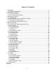
Table of Contents 1. Introduction ................................................................................................................. 3 1.1 Functions and Features ......................................................................................... 3 2. Hardware Installation................................................................................................... 5 2.1 Connect the Router...............................................................................................
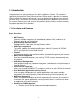
1. Introduction Congratulations on your purchase of this 802.11g Wireless Router. This product is specifically designed for Small Office and Home Office needs. It provides a complete SOHO solution for Internet surfing and is easy to configure and operate even for nontechnical users. Instructions for installing and configuring this product can be found in this manual. Before you install and use this product, please read this manual carefully for proper operation of this product. 1.
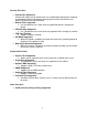
Security Functions • • • • • • Packet Filter Supported Packet Filter allows you to control access to a network by analyzing the incoming and outgoing packets and allowing or denying them access based on the IP address of the source and destination. Domain Filter Supported o Lets you prevent users from accessing specified domains through this device. URL Blocking Supported o Lets you prevent users from accessing specified URLs through this device. VPN Pass-Through o Support VPN pass-through.
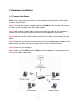
2. Hardware Installation 2.1 Connect the Router Note: Prior to connecting the router, be sure to power off your computer, DSL/Cable modem, and the router. Step 1 Connect one end of a network cable to the WAN port of the router and connect the other end of the cable to the DSL/Cable modem. Step 2 With another network cable, connect one end of the cable to your computer’s network card and connect the other end to one of the LAN ports of the router.
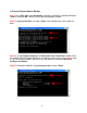
2.2 Verify Connection to Router Step 1 Go to Start, Run, type command (for Windows 95/98/ME) or cmd (for Windows 2000/XP) and click OK. You will see the command prompt as below. Step 2 Type ping 192.168.1.1 and press Enter. You should get four reply responses back. Step 3 If you get Request timed out, or Destination host unreachable, double-check the network cable connection between the computer and the router and try Step 2 again.
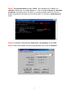
Step 5 Type ipconfig/renew and press Enter. You should get an IP address of 192.168.1.x (where x is a number between 2 - 254). Proceed to Section 3, Configure the Router. If you don’t get an IP address, reset the router by holding in the reset button at the back of the router for 10 seconds while it is ON and try ipconfig/renew again. Step 6 For Windows 95/98/ME go to Start, Run, type winipcfg and click OK. Step 7 Select your network card from the drop-down menu and click Release.
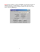
Step 8 After your IP address is released, click Renew. You should get an IP address of 192.168.1.x (where x is a number between 2 - 254). If you don’t get an IP address, reset the router by holding in the reset button at the back of the router for 10 seconds while it is ON and try Renew again.
3. Configure the Router 3.1 Setup Wizard Step 1 Open the web browser and type 192.168.1.1 in the URL Address field and press Enter. Step 2 Enter admin for the password field and click Log in. Step 3 Click on Wizard from the main menu and click Next to begin the Setup Wizard.
Step 4 Select your WAN Type (Internet Connection Type) and click Next. If you are not sure what your Internet Connection Type is, please contact your Internet Service Provider (ISP) for assistance. Cable Modem If you use cable modem, select Obtain an IP address from ISP automatically (Dynamic IP Address) and click Next. Proceed to Step 5a, Cable Modem. DSL If you use DSL, select Some ISPs require the use of PPPoE to connect to their services (PPP over Ethernet) and click Next. Proceed to Step 5b, DSL.
For Cable Modem Users: Step 5a If your ISP has provided you with a host name, enter it in the Host Name field. If your ISP requires a registered MAC Address, click on the Clone MAC button. Click Next when done and proceed to Step 6. For DSL Users: Step 5b Fill in the applicable fields according to the information provided by your ISP. Click Next when done and proceed to Step 6. Note: Depending on the ISP, you may need to include the domain name with your account name. Example: username@sbcglobal.
Step 6 Click Reboot to apply your settings. Step 8 Click OK to confirm reboot. Step 9 Wait for the router to reboot and proceed to Section 4, Verify Connection Status.
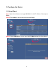
4. Verify Connection Status and Wireless Settings 4.1 Checking the System Status View the System Status to verify your Internet connection. Step 1 Login to the router’s web configuration page and click on the Status link from the Main Menu. Step 2 Verify that the WAN Status displays valid numbers (instead of all 0’s). If you use Cable modem and you see all 0’s, click on the Renew button. If you use DSL and you see all 0’s, click on the Connect button.
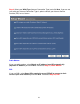
Step 3 Once you clicked the Renew or Connect button, you should see some numbers under WAN Status. This means you have successfully established Internet connection. Note: If you still see all 0’s after clicking on the Renew or Connect button, try the troubleshooting tips at the end of this manual. 4.2 Connecting to the Router Wirelessly Below are the default wireless settings of the router.
5. Web Configuration 5.1 Accessing the Web Configuration Utility You may configure the router through the web browser using the Web Configuration Utility. Step 1 Open the web browser and type in 192.168.1.1 and press Enter. Step 2 Enter admin for the password field and click Log in. You will see the Web Configuration Utility’s home page (System Status). You can navigate through the utility from the Main Menu located at the left side of the page.
5.2 Basic Setting 5.2.1 Primary Setup You can set the router’s LAN IP address and change the WAN type (Internet Connection Type) on this page. LAN IP Address: The router’s default IP address is 192.168.1.1. You can change this address to suit your existing network. WAN Type: Displays the current WAN type (Internet Connection Type) selected. Click the Change button to change the WAN type.
Static IP Address If your ISP assigns you static IP address, they will provide you the information for WAN IP Address, WAN Subnet Mask, WAN Gateway, Primary and Secondary DNS. Click Save to save any changes or click Undo to cancel any changes. Road Runner Enter the Account name and Password required to connect to your ISP. Some ISPs require an additional Login Server.
DSL (PPPoE) LAN IP Address: The router’s default IP address is 192.168.1.1. You can change this address to suit your existing network. Enter the Account name and Password required to connect to your ISP. Some ISPs require you to include the domain name with your account name in the Account name field. Example: username@sbcglobal.net Primary DNS and Secondary DNS: If your ISP provided you with the IP address of the Primary and Secondary DNS servers, you may enter them in the respective field.
PPTP Enter the information provided by your ISP in the respective fields. Connection ID (optional): Some ISPs require the use of a connection ID. Maximum Idle Time (in seconds): Enter the maximum idle time (in seconds) before the router disconnects the PPPoE session. Auto-reconnect (check box): Checking this box enables the router to automatically reconnect to the Internet once the connection is dropped. Click Save to save any changes or click Undo to cancel any changes.
Virtual Computers The Virtual Computer function enables you to map the Global IP (WAN IP address) assigned by your ISP to the Local IP (LAN IP address) of your computer. Global IP: Enter the global IP address (WAN IP) assigned by your ISP. Local IP: Enter the local IP address (LAN IP) of your computer you wish to map to. Enable (check box): Check this box to enable the Virtual Computer function. Click Save to save any changes or click Undo to cancel any changes.
5.2.2 DHCP Server This page allows you to configure the DHCP service of the router. DHCP assigns dynamic IP address to all the network devices connected to the router. DHCP Server: Select either to Enable or Disable the DHCP service (Default is Enable). IP Pool Starting Address: Enter the start of the IP pool range. IP Pool Ending Address: Enter the end of the IP pool range. Domain Name: Enter the domain name of your network (optional). Click on the More>> button to see the following fields.
Clients List The Clients List displays all the DHCP clients currently connected to the router. To perform the first two functions, select a client from the list first. Wake up: Sends a wake up packet to the target client. The target client must support the wake up function. Delete: Deletes the client from the list. Back: Returns to the previous page. Refresh: Updates the Clients List. 5.2.3 Wireless This page allows you to configure the router’s wireless security.
Channel: Select a transmission channel for wireless communications. The channel of any wireless clients must match the channel selected here in order for the wireless clients to access the router. Security: Select the best encryption method supported by your wireless network adapter. Disable: No wireless encryption enabled. WEP: Select to enable WEP encryption. Select to enable either 64 bit or 128 bit encryption. WEP Key 1 ~ Key 4: Enter a value for each key.
802.1x and RADIUS: Select this option only if you are using a RADIUS server for authentication. Encryption Key Length: Select either 64 bit or 128 bit encryption. RADIUS Server IP: Enter the IP address of your RADIUS server. RADIUS port: Enter the port number of your RADIUS server. RADIUS Shared Key: Enter the RADIUS shared key. WPA-PSK: Select this option if your wireless network adapter supports WPA. Preshare Key: Enter a preshare key (password) for your wireless encryption.
WPA: Select this option only if you are using WPA with a RADIUS server for authentication. RADIUS Server IP: Enter the IP address of your RADIUS server. RADIUS port: Enter the port number of your RADIUS server. RADIUS Shared Key: Enter the RADIUS shared key. 5.2.4 Change Password This page allows you to change the router’s login password. It is recommended that you change the login password for extra security. Old Password: Enter the current login password. New Password: Enter the new login password.
5.3 Forwarding Rules 5.3.1 Virtual Server If you want to allow Internet users to access your internal web server or ftp server, you can use the Virtual Server function to open up the ports required to access your internal servers. Service Ports: Enter the service port you wish to open to the Internet. Server IP: Enter the LAN IP address of the server you want the Internet users to access. Enable (check box): Check on this box to open the port.
Schedule rule: If you have configured any schedule rule, you can select the rule from this list and apply the rule to the specified ID. For more information about using the schedule rule, please see 5.5.6 Schedule Rule. Click Save to save any changes or click Undo to cancel any changes. 5.3.2 Special AP Some applications require multiple connections, like Internet games, video conferencing, Internet telephony, etc.
5.3.3 Miscellaneous DMZ (De-Militarized Zone) Host is a host without the protection of the router’s firewall. It allows a computer to be exposed to unrestricted two-way communication with the Internet. You should only use this feature when the Special Applications function fails to make an application work. Warning: Setting your computer as a DMZ host exposes it to various security vulnerabilities. This feature should be used only when needed.
5.4 Security Setting 5.4.1 Packet Filter Packet Filter enables you to control which packets are allowed to pass through the router. Outbound filter applies on all outbound packets. However, Inbound filter applies to packets that are destined to Virtual Servers or DMZ host only. Outbound Packet Filter is the default packet filter page. To change to Inbound Packet Filter, click on the Inbound Filter button. You can select one of the two filtering policies: 1.
For source or destination IP address, you can define a single IP address (192.168.1.100) or a range of IP addresses (192.168.1.100-192.168.1.254). An empty field implies all IP addresses. For source or destination port, you can define a single port (80) or a range of ports (1000-1999). Add the prefix "T" or "U" to specify TCP or UDP protocol. For example: T80, U53, or U2000-2999. No prefix indicates both TCP and UDP are defined. An empty field implies all ports.
5.4.2 Domain Filter Domain Filter lets you prevent users from accessing any specified domain. Domain Filter: Check the Enable box to activate the Domain Filter function. Log DNS Query: Check the Enable box to log the action of someone trying to access the specified domain. Privilege IP Addresses Range: Any IP address that falls between the specified range will be exempt from the domain filter. Domain Suffix: Enter any domain suffix you wish to filter. For example: something.
5.4.3 URL Blocking URL Blocking will block the local computers from accessing pre-defined web sites. The main difference between Domain filter and URL Blocking is that Domain filter requires you to input a suffix like .com or .org, etc., while URL Blocking only requires you to input a keyword. In other words, Domain filter can block a specific web site, while URL Blocking can block hundreds of web sites that contain the specified keyword.
5.4.4 MAC Address Control MAC Address Control allows you to assign different access rights for different users and to assign a specific IP address to a certain MAC address. MAC Address Control: Check the Enable box to activate the MAC Address Control function. Connection control (check box): Check this box to specify which clients are allowed or denied connection to the router.
5.4.5 Miscellaneous Items Remote Administrator Host/Port: In general, only local users can browse the router’s built-in web configuration utility to perform administration tasks. Remote Administration enables you to perform administrative tasks from remote host. If this feature is enabled, only the host with the specified IP address can perform remote administration. If the specified IP address is 0.0.0.0, any host can connect to the router to perform administrative tasks.
5.5 Advanced Settings 5.5.1 System Time This page allows you to configure the system time of your router. Get Date and Time by NTP Protocol: Select this option if you want to obtain the time from a Network Time Server. Time Server: Select the time server you want to sync with. Time Zone: Select your time zone. Click the Sync Now! button to obtain the time from the selected time server. Set Date and Time using PC’s Date and Time: Select this option if you want to obtain the time from your PC.
5.5.2 System Log This page allows you to export the system logs to specific destination by means of syslog (UDP) and SMTP (TCP). IP Address for Syslog: Enter the destination IP Address where the syslog will be sent to. Be sure to check the Enable box. IP Address of Outgoing Mail Server: Input the SMTP server IP and port. If you do not specify a port number, the default value (25) is used. Log or Alert Recipient: Enter the e-mail address of the recipient who should receive the logs or alerts.
5.5.3 Dynamic DNS Dynamic DNS allows any user who wishes to access your server to reach it by a registered DNS name instead of an IP address. Before you enable Dynamic DNS, you need to register an account with one of the Dynamic DNS servers listed in the Provider field. DDNS: Choose to enable or disable DDNS. Provider: Select the DDNS provider that you registered the account with. Enter your Host Name, Username, and password for the DDNS account in the respective fields.
5.5.4 SNMP Enable SNMP: select to enable SNMP for local and/or remote segments.
5.5.5 Routing The Routing Table allows you to set which network interface address to use for outgoing IP data grams. If you have more than one router and subnet, you will need to configure the routing table to direct the packets to follow the proper routing path so different subnets can communicate with each other. You can specify up to 8 routing rules. Enter the destination IP address, subnet mask, gateway, and the hop required for each rule. Check the Enable box to activate the rule.
5.5.6 Schedule Rule The Schedule Rule allows you to set the time when certain services will be on or off. Schedule Rule works in conjunction with Virtual Server and Packet Filter to determine when these services will be active or inactive. Schedule: Check the Enable box to activate the Schedule Rule function. Click on Add New Rule button to add a new schedule rule. Name of Rule: Enter a descriptive name for the new rule. Set the day and time that the rule applies to.
Once you have created the new rule, you can call up this rule from the Virtual Server and Packet Filter page and apply the schedule rule to any IDs in the Virtual Server or Packet Filter page. Example of using the Schedule Rule with Virtual Server: Suppose you’ve set up a FTP server in the Virtual Server page, but you only want users to access the FTP server everyday between the hours of 2:00 pm to 6:00 pm.
5.6 Toolbox 5.6.1 View Log This page allows you to view the System Log. Back: Returns to the previous page. Refresh: Updates the log. Download: Saves the log to a specified location. Clear logs: Deletes the log from the system.
5.6.2 Firmware Upgrade This page allows you to update the router’s firmware. 1. 2. 3. 4. Download the latest firmware from www.airlink101.com web site. Click the Browse button to locate the firmware. Be sure to unzip the file first. Click on Upgrade. Wait for the upgrade process to complete.
5.6.3 Backup Setting Once you have configured all of the router’s settings, you can backup the settings as a file on your hard drive. (The file will be named config.bin). When you want to restore the saved settings, go to the firmware upgrade page and browse to the config.bin file. 5.6.4 Reset to Default Click OK to restore all settings to factory default. 5.6.5 Reboot Click OK to reboot the router.
5.6.6 Miscellaneous Items Wake-on-LAN is a technology that enables you to power up a network device remotely. In order to use this feature, the target device must be Wake-on-LAN enabled and you have to know the MAC address of the device, i.e. 00-11-22-33-44-55. Clicking the Wake up button will make the router send a wake-up frame to the target device immediately. 6. Troubleshooting For Cable Modem Users Only Step 1 Go to the router’s Setup Wizard.
For DSL Users Only Step 1 Go to the router’s Setup Wizard. Step 2 At the PPPoE setting, double-check the spelling of your Account name and Password. Some ISPs require you to include the domain name along with your account name in the Account Name field. Example: username@sbcglobal.net Step 3 Complete the Setup Wizard and verify the Connection Status as described in Section 4. For Cable Modem and DSL Users Step 1 Power off the Cable/DSL modem, router, and computer and wait for 5 minutes.
Appendix Technical Support E-mail: support@airlink101.com Toll Free: 1-888-746-3238 Web Site: www.airlink101.com *Theoretical maximum wireless signal rate based on IEEE standard 802.11g specifications. Actual data throughput will vary. Network conditions and environmental factors, including volume of network traffic, building materials and construction, mix of wireless products used, radio frequency interference (e.g.