Wireless N 150 Router Model # AR570W User’s Manual Ver.
Federal Communication Commission Interference Statement FCC Part 15 This equipment has been tested and found to comply with the limits for a Class B digital device, pursuant to Part 15 of FCC Rules. These limits are designed to provide reasonable protection against harmful interference in a residential installation. This equipment generates, uses, and can radiate radio frequency energy and, if not installed and used in accordance with the instructions, may cause harmful interference to radio communications.
Table of Contents FEDERAL COMMUNICATION COMMISSION INTERFERENCE STATEMENT............................2 TABLE OF CONTENTS .....................................................................................................................3 CHAPTER 1 INTRODUCTION...........................................................................................................6 1.1 FEATURES ................................................................................................................................
3.5.1 Firewall ..................................................................................................................................... 66 3.5.2 DoS (Denial-of-Service) ......................................................................................................... 67 3.5.2.1 DoS – Advanced Settings................................................................................................... 67 3.5.3 VPN Pass through ................................................................
Chapter 1 Introduction Congratulations on your purchase of Airlink101 Wireless N 150 Router AR570W. This product is ideal for home or SOHO users who need greater bandwidth and higher speed for various networking applications, such as VoIP phone, online gaming or online video/audio streaming. Based on Wireless N technology, the data throughput is up to 3 times faster than Wireless G. It is recommended to use with AirLink101® Wireless N or Wireless N 150 adapters to reach the best performance.
LED Light Status Description POWER On Router is powered on. On WPS setup is in progress. Off Wireless network is switched off. Flashing Wireless network is ready and WPS setup is not in progress. On WAN port is connected. Off WAN port is not connected. Flashing WAN port is transferring or receiving data. On LAN port is connected. Off LAN port is not connected. Flashing LAN port is transferring or receiving data.
Reset / WPS Reset the router to factory default settings (clear all settings) or start security synchronization function (WPS). Press this button and hold for 10 seconds to restore all settings to factory defaults. Press this button for no longer than 1 second to start security synchronization. 1-4 Local Area Network (LAN) ports 1 to 4. WAN Wide Area Network (WAN / Internet) port. Power Power connector, connects to A/C power adapter.
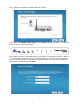
Chapter 2 Installing the Router 2.1 Using EZ Setup Wizard Step 1 Insert the Setup CD into your CD-ROM drive. Step 2 Click Next to start the configuration.
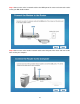
Step 3 Connect one end of a network cable to the WAN port of the router and connect the other end to your DSL/Cable modem. Step 4 Connect one end of another network cable to the LAN port of the router and connect the other end to your computer.
Step 5 Power on the Router. It will take about 30 seconds. Step 6 Make sure POWER, WAN, WLAN, and the LAN port that the computer is connected to are lit. If not, try the above steps again. Step 7 Enter the Router’s password to log in to the Router. The default password is “admin”. It is recommended to change the router’s password to protect it from being accessed by other users. If you do not wish to change the current password, you can leave New Password and Confirm New Password blank. Click Next.
Step 8 Verify the Internet Connection Type the wizard detected. If it is not correct, please configure it manually. Click Next. Note: If you are not sure which Internet Connection Type you use, please contact your Internet Service Provider for this information. Step 9 Enter the settings for your Internet Connection Type. Dynamic IP (Cable Modem users) Click on Clone to clone the MAC address of your PC to the modem then click Next.
Step 10 Please wait while the Wizard trying to connect to the Internet. If you see the window “Internet Connection Succeed”, your router has been successfully connected to the Internet. Please click Next to configure the wireless settings.
Step 11 Configure a name for your wireless network. Click Next. Step 12 Configure the security key for your wireless network. Check Enable WPA Pre-Share Key. Enter 8 to 63 characters into WPA-Pre-Share Key. Click Next.
Step 13 Verify the settings you just configured for the Router. Click Finish to restart the Router. Congratulations! Your router configuration has been finished.
2.2 Connecting to the Router Wirelessly You must configure your wireless computer in order to establish a wireless connection to the router. In this section, you can find the instructions of how to connect to the router wirelessly with your Vista computer. You can also refer to the manual of your wireless network card regarding how to connect to a router wirelessly. Step 1 Click on this icon are available.
Step 3 Enter the Security key you configured for the Router (see Step 12 in Chapter 2.1). Click Connect. Step 4 Click on Close. Now the wireless connection has been established successfully with the Router. You should be able to connect to Internet wirelessly now.
Chapter 3 Using Web Configuration Utility The Web Configuration Utility contains advanced features that allow you to configure the router to meet your network’s needs such as: Access Control, QoS (Quality of Service), Port Forwarding (Virtual Server) and other functions. If you have already gone through the EZ Setup Wizard, you do NOT need to configure any other thing here for you to start using the Internet. Below is a general description of the advanced functions available for this router.
Step 2 Enter your user name and password and click OK. (The default user name and password are both “admin”.) Step 3 When you see this page coming up, you have successfully logged in to the router. You can now access the complete features/settings of the router.
3.0 Setup Wizard Click on Setup Wizard and start the basic configuration for this router. If you have gone through the EZ Setup Wizard on the provided CD, you do not need to set up the router again. Step 1 Configure the Time Zone Settings of the Router. You can click on Copy Time from PC. Enable Daylight Saving if it is applicable in your country. Click NEXT.
Time Server Address Input the IP address / host name of time server here Daylight Savings If the country you live uses daylight saving, please check the Enable box and choose the duration of daylight saving. Step 2 Select WAN type by which Internet service you are using. Dynamic IP (for Cable or some DSL users) Click on Dynamic IP if you are connecting to Internet through a cable modem. When the Dynamic IP settings appear below, click Clone MAC and click NEXT.
Primary DNS Please input the IP address of DNS server provided by your service provider. Secondary DNS Please input the IP address of another DNS server provided by your service provider, this is optional. PPPoE (for DSL users) For DSL users, your Internet type is either Dynamic IP or PPPoE.
Password Please input the password assigned by your Internet service provider here. DNS Address Select the type of how you obtain IP address from your service provider here. You can choose “Obtain an IP address automatically”, or “Use the following IP address” (i.e. static IP address). Primary DNS Please input the IP address of DNS server provided by your service provider. Secondary DNS Please input the IP address of another DNS server provided by your service provider, this is optional.
PPTP PPTP requires two kinds of setting: WAN interface setting (setup IP address) and PPTP setting (PPTP user name and password). Here we start from WAN interface setting: Select the type of how you obtain IP address from your service provider here. You can choose “Obtain an IP address automatically, or “Use the following IP address” (i.e. static IP address) for IP and DNS address.
Connection ID Please input the connection ID here, this is optional and you can leave it blank. MTU Please input the MTU value of your network connection here. If you don’t know, you can use default value. BEZEQ-ISRAEL Setting item BEZEQ-ISRAEL is only required to check if you’re using the service provided by BEZEQ network in Israel. Connection Type Please select the connection type of Internet connection you wish to use, please refer to last section for detailed descriptions.
Parameter Description User Name Please input user name assigned by your Internet service provider here. Password Please input the password assigned by your Internet service provider here. L2TP Gateway Please input the IP address of L2TP gateway assigned by your Internet service provider here. MTU Please input the MTU value of your network connection here. If you don’t know, you can use default value.
Password Please input the password assigned by Telstra. Assign login server manually Check this box to choose login server by yourself. Server IP Address Please input the IP address of login server here. When you finish with all settings, please click NEXT. Step 3 Keep the default LAN IP and DHCP server settings or modify as needed. Click NEXT. Step 4 Keep the default SSID (wireless network name) or change it to a desired name, so you can always recognize your wireless network with it. Click NEXT.
2.4GHz (B): 2.4GHz band, only allows 802.11b wireless network client to connect to this router (maximum transfer rate 11Mbps). 2.4 GHz (N): 2.4GHz band, only allows 802.11n wireless network client to connect to this router (maximum transfer rate 150Mbps). 2.4 GHz (B+G):2.4GHz band, only allows 802.11b and 802.11g wireless network client to connect to this router (maximum transfer rate 11Mbps for 802.11b clients, and maximum 54Mbps for 802.11g clients). 2.4 GHz (G): 2.4GHz band, only allows 802.
WPA2(Mixed) Select WPA pre-shared key for Encryption. Enter the settings below: • • • WPA Unicast Cipher Suite: Select WPA2(Mixed) Pre-Shared Key Format: Select Passphrase Pre-shared Key: Enter a key between 8 to 63 characters (alphanumeric, case sensitive). This is the security key for your wireless network Click OK to save the settings.
If each field has valid numbers or IP addresses being assigned, the router is connected to the Internet.
3.1 Network 3.1.1 WAN Use the WAN setting page to change your Internet connection type. The WAN setting page allows you to configure the Internet connection type of your ISP. The WAN settings offer the following selections for the router’s WAN port, Dynamic IP, Static IP, PPPoE, PPTP, L2TP and Telstra Big Pond. Please choose one type and complete the detail settings below. Please see Step 2 in the previous chapter, 3.0 Setup Wizard for the detailed description of each WAN type. 3.1.
¾ LAN IP section Parameters IP address Subnet Mask 802.1d Spanning Tree DHCP Server Default 192.168.2.1 255.255.255.0 Disable Enable Description This is the router’s LAN IP address (Your LAN clients’ default gateway IP address). Specify a Subnet Mask for your LAN segment. If you wish to activate 802.1d spanning tree function, select “Enabled”, or set it to “Disabled” If 802.
¾ DHCP Server section Parameters Description Lease Time Please choose a lease time (the duration that every computer can keep a specific IP address) of every IP address assigned by this router from dropdown menu. DHCP Client Start IP Please input the start IP address of the IP range. DHCP Client End IP Please input the end IP address of the IP range. Domain Name If you wish, you can also optionally input the domain name for your network. This is optional.
If you want to delete a specific item, please check the “Select” box of a MAC address and IP address mapping, then click “Delete” button. If you want to delete all mappings, click “Delete All”. After you finish with all settings, please click “Apply” button. If you want to reset all settings in this page, please click “Cancel” button.
Parameter Description Enable Static Routing Check/uncheck to disable/enable the NAT function. Destination LAN IP Enter the IP Address of the destination LAN. Subnet Mask Enter the Subnet Mask of the destination LAN. Default Gateway This is the gateway IP Address where packets are sent. Input the gateway IP Address. Hop Count Enter the maximum number of steps between network nodes that data packets will travel. A node is any device on the network, such as a computer, print server, or router.
Reset You can also click ‘Reset’ button unselect all. After you finish with all settings, please click “Apply” button. If you want to reset all settings in this page, please click “Cancel” button.
Provider Select a DDNS service provider. Domain name Your static domain name that use DDNS. Account The account/username that your DDNS service provider assigned to you. Password/Key The password you set for the DDNS service account above. After you finish with all settings, please click “Apply” button. If you want to reset all settings in this page, please click “Cancel” button.
3.2 Wireless 3.2.1 Basic Settings You can set parameters that are used for wireless clients to connect to this router. The parameters include SSID, Channel Number, etc. Parameters Band Default 2.4 GHz (B+G+N) Description Please select the radio band from one of the following options. 2.4GHz(B): 2.4GHz band, only allows 802.11b wireless network client to connect this router (maximum transfer rate 11Mbps*). 2.4 GHz (N): 2.4GHz band, only allows 802.
SSID Channel Number airlink101 This is the name of your wireless network. You can type any alphanumerical characters here, maximum 32 characters. SSID is used to identify your own wireless router from others when there are other wireless routers in the same area. It’s recommended to change default SSID value to the one which is meaningful to you, like myhome, office_room1, etc. 6 Please select a channel from the dropdown list of ‘Channel Number’ for broadcasting.
Parameters Default Description Encryption You can choose Disable, WEP, WPA pre-share key, WPA RADIUS for encryption mode. The detailed settings will appear after you choose an encryption. See 3.2.2.1 to 3.2.2.3 for each encryption type. Enable 802.1x Authentication IEEE 802.1x is an authentication protocol. Every user must use a valid account to login to this Access Point before accessing the wireless LAN. The authentication is processed by a RADIUS server.
3.2.2.1 WEP Select “WEP” for the “Encryption” mode if you wish to use WEP to encrypt your wireless network. Parameters Description Key Length You can select the WEP key length for encryption, 64-bit or 128bit. Larger WEP key length will provide higher level of security, but the throughput will be lower. Key Format You may select to select ASCII Characters (alphanumeric format) or Hexadecimal Digits (in the “A-F”, “a-f” and “0-9” range) to be the WEP Key.
change the encryption key frequently. So the encryption key is not easy to be broken by hackers. This can improve security very much. Select “WPA Pre-share Key” for the “Encryption” mode if you wish to use WPA-PSK or WPA2PSK to encrypt your wireless network. Parameters Description WPA Unicast Cipher Suite Available options are: WPA (TKIP), WPA2 (AES), and WPA2 Mixed. WPA2 (Mixed) support both WPA-PSK(TKIP/AES) and WPA2-PSK(TKIP/AES).
Parameters Description WPA Unicast Cipher Suite Please select a type of WPA cipher suite. Available options are: WPA (TKIP), WPA2 (AES), and WPA2 Mixed. You can select one of them, but you have to make sure your wireless client support the cipher you selected. RADIUS Server IP Address Please input the IP address of your Radius authentication server here. RADIUS Server Port Please input the port number of your Radius authentication server here. Default setting is 1812.
Parameters Description Enable MAC Control Check/Uncheck to enable/disable wireless MAC control. MAC Address Input the MAC address of your wireless devices here, format ‘xx:xx:xx:xx:xx:xx’. Comment You can input any text here as the comment of this MAC address, like ‘ROOM 2A Computer’ or anything. Add Click “Add” button to add the MAC address and associated comment to the MAC address filtering table. Clear Click “Clear” to remove the value you inputted in MAC address and comment field.
You can click “Continue” to back to previous setup page to continue on other setup procedures, or click “Apply” to reboot the router so the settings will take effect (Please wait for about 30 seconds while router is rebooting). 3.2.4 Advanced Settings You can set advanced wireless LAN parameters of this router. The parameters include Authentication Type, Fragment Threshold, RTS Threshold, Beacon Interval, Preamble Type, etc.
RTS Threshold When the packet size is smaller than the RTS threshold, the wireless router will not use the RTS/CTS mechanism to send this packet. Beacon Interval The interval of time that this wireless router broadcast a beacon. Beacon is used to synchronize the wireless network. DTIM Period Set the DTIM period of wireless radio. Do not modify default value if you don’t know what it is, default value is 3. Data Rate Set the wireless data transfer rate to a certain value.
You can click “Continue” to back to previous setup page to continue on other setup procedures, or click “Apply” to reboot the router so the settings will take effect (Please wait for about 30 seconds while router is rebooting). 3.2.5 WPS The Airlink101 Wireless 150 Router AR570W has a built-in Easy Setup Button which allows you to connect your wireless computer with the router easily and safely. Your wireless adapter must support this feature as well.
Step 2 Push and hold the Easy Setup Button on the Adapter until you see the following window pops up on the computer monitor. Step 3 Within the following 2 minutes, push the Easy Setup Button the Router. The WLAN LED will stay solid green instead of blinking. Step 4 The Router will now start the handshake with the wireless adapter which will take about 30 seconds. When you see the window similar to the one below, the connection has been established.
Parameters Description Enable WPS Check this box to enable WPS function, uncheck it to disable WPS. Wi-Fi Protected Setup Information WPS-related system information will be displayed here: WPS Status: If the wireless security (encryption) function of this wireless router is properly set, you’ll see “Configured” message here. If wireless security function has not been set, you’ll see “unConfigured”. Self PIN code: This is the WPS PIN code of this wireless router.
Configure by Push Button Click “Start PBC” to start Push-Button style WPS setup procedure. This wireless router will wait for WPS requests from wireless clients for 2 minutes. The “WLAN” LED on the wireless router will be steady on for 2 minutes when this wireless router is waiting for incoming WPS request. Configure by Pin Code Please input the PIN code of the wireless client you wish to connect, and click “Start PIN” button.
3.3 Application & Gaming 3.3.1 Virtual Server (Port Forwarding) The Virtual Server allows you to re-direct a particular range of service port numbers (from the Internet/WAN Ports) to a particular LAN IP address. It helps you to host some servers behind the router NAT firewall. Parameter Description Enable Virtual Server Enable Virtual Server (Port Forwarding) Private IP This is the private IP address of the server behind the NAT firewall.
Public Port Input the port number of Internet IP address which will be redirected to the port number of local IP address defined above. Comment The description of this setting. Current Virtual Server Table From the table, you can check each Virtual Server setting. Delete If you want to delete a setting, check the ‘select’ box of the setting you want to delete, then click ‘Delete’ button. (You can select more than one setting).
Parameter Description Enable Special Applications Check to enable Special Applications, or uncheck to disable. IP Address This is the private IP of the computer/server behind the NAT firewall. Note: You need to give your PC a fixed/static IP address for Special Applications to work properly. Computer Name This is the computer that you need to enable the Special Application function.
From the Current Trigger-Port Table, you can select each Special Application setting by checking the “Select” checkbox. Parameter Description Delete If you want to delete a setting, check the ‘select’ box of the setting you want to delete, then click ‘Delete’ button. (You can select more than one setting). Delete All If you want to delete all settings listed here, please click ‘Delete All’ button. Reset You can also click ‘Reset’ button to unselect all.
Parameter Description Enable DMZ Check/uncheck to enable/disable DMZ. Public IP You can select “Dynamic IP” or “Static IP” here. If you select “Dynamic IP”, you have to select an Internet connection session from drop down menu; if you select “Static IP”, please input the IP address that you want to map to a specific private IP address. Client PC IP address Please input the private IP address that the Internet IP address will be mapped to.
Reset You can also click ‘Reset’ button to unselect all. After you finish with all settings, please click “Apply” button. If you want to reset all settings in this page, please click “Cancel” button.
There are many applications listed here. Please check the box of the special support for applications you need. After you finish with all settings, please click “Apply” button. If you want to reset all settings in this page, please click “Cancel” button.
Parameter Description Enable QoS Check this box to enable QoS, and uncheck this box to disable QoS. Total Download Bandwidth You can set the limit of total download bandwidth in kbits. To disable download bandwidth limitation, input 0 here. Total Upload Bandwidth You can set the limit of total upload bandwidth in kbits. To disable upload bandwidth limitation, input 0 here. Current QoS Table From the table, you can check each QoS rule setting.
Parameter Description Rule Name Please give a name to this QoS rule (up to 15 alphanumerical characters). Bandwidth Set the bandwidth limitation of this QoS rule. You have to select the data direction of this rule (Upload of Download), and the speed of bandwidth limitation in Kbps, then select the type of QoS: “guarantee” (guaranteed usable bandwidth for this rule) or “max” (set the maximum bandwidth for the application allowed by this rule).
the limitation on all traffics from / to the specified IP address / port number), select “None”. Protocol Please select the protocol type of this rule, available options are TCP and UDP. If you dont know what protocol your application uses, please try “TCP” first, and switch to “UDP” if this rule doesn’t seems to work.
3.4 Access Restrictions This function allows you to configure some Internet access rules for your local computers based on the IP address, applications, URL or keywords. 3.4.1 IP & Port Filtering If you want to restrict users from accessing certain Internet applications/services (e.g. Internet websites, email, FTP etc.) by their IP addresses, then you can set up the filtering rules here. Entries in this table are restricted to use certain type of connections from the router.
Parameters Description Client PC Description Please input any text to describe this IP address, up to 16 alphanumerical characters. Client PC IP address Please input the starting IP address in the left field, and input the end IP address in the right field to define a range of IP addresses, or just input the IP address in the left field to define a single IP address. Client Service Please check all services you want to allow or deny this IP address to use, you can check multiple services.
Add When you finish with all settings, please click “Add” to save settings, you’ll be brought back to previous menu, and the rule you just set will appear in current IP filtering table. After you finish with all settings, please click “Apply” button. If you want to reset all settings in this page, please click “Cancel” button.
Parameters Description Enable MAC Filtering Check this box to enable the MAC filtering function. Please select “Deny” or “Allow” to decide the behavior of MAC filtering table. If you select Deny, all MAC addresses listed in filtering table will be denied from connecting to the network; if you select Allow, only MAC addresses listed in filtering table will be able to connect to the network, and all other network devices are rejected.
Parameter Description Enable URL Filtering Enable/Disable URL Blocking. URL/Keyword You can enter the full URL address of a website or any keyword of certain web contents you want to block. Current URL Blocking Table From the table, you can check each URL filter setting. Delete If you want to delete a setting, check the ‘select’ box of the setting you want to delete, then click ‘Delete’ button. (You can select more than one setting).
3.5 Security 3.5.1 Firewall Excepting NAT, this router also provides firewall function to block malicious intruders from accessing your computers on local network. These functions include inbound attack prevention, and block outbound traffics. The Wireless 150 Router AR570W has built in SPI Firewall which is a type of firewall that inspects incoming data packets to make sure they correspond to an outgoing request. Unsolicited and possibly harmful packets are rejected.
3.5.2 DoS (Denial-of-Service) Denial of Service (DoS) is a common attack measure, by transmitting a great amount of data or request to your Internet IP address and server, the Internet connection will become very slow, and server may stop responding because it is not capable to handle too much traffics. This router has a built-in DoS attack prevention mechanism; when you activate it, the router will stop the DoS attack for you.
Parameter Description Ping of Death Set the threshold of when this DoS prevention mechanism will be activated. Please check the box of Ping of Death, and input the frequency of threshold (how many packets per second, minute, or hour), you can also input the ‘Burst’ value, which means when this number of ‘Ping of Death’ packet is received in very short time, this DoS prevention mechanism will be activated.
You can click “Continue” to back to previous setup page to continue on other setup procedures, or click “Apply” to reboot the router so the settings will take effect (Please wait for about 30 seconds while router is rebooting). 3.5.3 VPN Pass through Parameter Description IPsec pass through Check this box and the router will enable IPsec packets pass through the router for VPN connection.
3.6 Administration The Administration page allows you to specify a time zone, to change the system password and to specify a remote management port, to upgrade firmware, to save/reload configuration settings, to enable system log, to view the statistics information, and to enable/disable UPnP for the Router. 3.6.1 Time Parameter Description Current Time Display the router’s current time. You can manually configure it or Click on Copy Time from PC.
You can click “Continue” to back to previous setup page to continue on other setup procedures, or click “Apply” to reboot the router so the settings will take effect (Please wait for about 30 seconds while router is rebooting). 3.6.2 Management 3.6.2.1 Password You can change the password required to log into the Router’s web configuration utility. The default user name and password are “admin”.
After you finish with all settings, please click “Apply” button. If you want to reset all settings in this page, please click “Cancel” button. After you clicked Apply, the following message will be displayed on your web browser: You can click “Continue” to back to previous setup page to continue on other setup procedures, or click “Apply” to reboot the router so the settings will take effect (Please wait for about 30 seconds while router is rebooting). 3.6.2.
3.6.3 Remote Management You can manage this router remotely by enabling the ‘Remote Management’ function. Parameters Description Host Address Input the IP address of the remote host you wish to initiate a management access. “0.0.0.0” means any remote IP address. If you specify an IP address here, then the router will only allow remote access from this specific IP address. Port You can define the port number this router should expect an incoming request.
You can click “Continue” to back to previous setup page to continue on other setup procedures, or click “Apply” to reboot the router so the settings will take effect (Please wait for about 30 seconds while router is rebooting). 3.6.4 Firmware Upgrade To upgrade the firmware for the Router, you need to download the firmware file and save it to your local hard disk first. You may need to unzip it if it is a .zip file. Click NEXT to start the firmware upgrade.
3.6.5 Configuration Settings The Configuration Settings screen allows you to save (Backup) the router’s current configuration setting. Saving the configuration settings provides an added protection and convenience should problems occur with the router and you have to reset to factory default. When you save the configuration settings (Backup) you can re-load the saved settings into the router through the Restore function.
3.6.6 Log All important system events and system security are logged. You can use this function to check the log of your router. Parameters Description Save Save current event log to a text file. Clear Delete all event logs displayed here. Refresh Refresh the event log display.
3.6.7 Statistics View the statistics of packets sent and received on WAN, LAN and Wireless LAN. Click Refresh to display the latest information.
3.7 Status The Status section allows you to monitor the current status of your router. You can use the Status page to monitor: the Internet, LAN connection, Wireless status, and the current firmware version of the Router. 3.7.1 Internet Connection Status You can use this function to view the status of current Internet connection. 3.7.2 LAN Status You can use this function to view the LAN status of your router, including TCP/IP setting, DHCP Server status, and MAC address. 3.7.
You can use this function to show the Wireless LAN status of your router, including ESSID (the name of your wireless network), Channel number, and Security. 3.7.4 System Status You can use this function to know the system information and firmware version (Runtime Code Version) of this router.
Chapter 4 Troubleshooting If you have trouble connecting to the Internet, try the following steps: Step 1 Power off the Cable/DSL modem, router, and computer and wait for 5 minutes. Step 2 Turn on the Cable/DSL modem and wait for the lights on the modem to settle down. Step 3 Turn on the router and wait for the lights on the router to settle down. Step 4 Turn on the computer. Step 5 Log in to the router and you will see the Internet Connection Status.
Technical Support E-mail: support@airlink101.com Toll Free: 1-888-746-3238 Website: www.airlink101.com *Theoretical maximum wireless signal rate derived from IEEE standard 802.11 specifications. Actual data throughput will vary. Network conditions and environmental factors, including volume of network traffic, building materials and construction, mix of wireless products used, radio frequency interference (e.g.