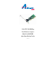
32-bit PCI 10/100Mbps Fast Ethernet Adapter Model # ASOHORL Quick Installation Guide Ver.
FCC Class B Certification This equipment has been tested and found to comply with the regulations for a Class B digital device, pursuant to Part 15 of the FCC Rules. These limits are designed to provide reasonable protection against harmful interference when the equipment is operated in a commercial environment. This equipment generates, uses, and can radiate radio frequency energy and, if not installed and used in accordance with this user’s guide, may cause harmful interference to radio communications.
Introduction Thank you for choosing the 32-bit PCI 10/100Mbps Fast Ethernet Adapter, this Adapter is auto-configurable upon power up and also supports auto-negotiation to automatically select the optimum speed and communication mode of an attached device. Additionally, the 32-bit PCI-Bus 10/100Mbps NWay ACPI Fast Ethernet Adapter complies with ACPI, and PC99, and includes support for Remote Wake-Up by Magic Packet™, LinkChg and Microsoft®wake-up frame.
Remote LAN Wakeup Remote LAN Wakeup capability is a key feature of a centrally managed PC environment. This technology allows networked PCs to be powered up and managed from a central location at any time. To utilize Remote LAN Wakeup, three elements are required: Desktop management software that can send a “wake-up” packet to the PC. A Wake-On-LAN enabled PC motherboard that can supply low-level auxiliary power to a network Adapter when the PC is powered off.
Product Featues Designed for versatility and performance, the 32-bit PCI bus 10/100Mbps Fast Ethernet Adapter provides the following features: • Compliant to IEEE 802.3, 10BASE-T standard • Complaint to IEEE 802.3u 100BASE-TX standard • Compliant to IEEE ANSI/802.3 NWay Auto-negotiation standard • Compliant to PCI 2.1, 2.
Installation Installation the 10/100Mbps PCI bus Fast Ethernet Adapter requires Hardware installation first, then BIOS and Software installation. Step 1, Hardware Installation 1. 2. 3. 4. 5. 6. Switch off the computer, unplug the power cord, and remove the computer’s cover. Select an unused PCI slot and remove its protective bracket. Carefully insert the Adapter and press until all the edge connectors are firmly seated inside the slot. Then, screw the Adapter’s bracket securely into the PC’s chassis.
Step 2, BIOS Configuration Due to a fault in some Plug-n-Play BIOS programs, it happens occasionally that a newly installed adapter is assigned an Interrupt Number which is already assigned to another device. In such a case, the conflict of Interrupt Number will cause faults in the behavior of both devices. In that case, it is necessary to run the CMOS Setup utility, and manually assign a non-conflicting Interrupt Number.
1. Insert the Boot ROM into the socket on the Adapter. 2. Refer to the installation procedures provided by the network operating system. Troubleshooting If you experience any problems with the Adapter, first verify that the appropriate driver is loaded, that the proper grade of cable is employed for the network connection, and that the supporting hub is functioning properly. 1. Verify that the Adapter is fully and firmly seated in the slot connector. 2.
test is not normal, then there is probably an interrupt number conflict which will have to be resolved manually by the CMOS Setup utility after you have reinstalled all of the expansion Adapters. Technical Support E-mail: support@airlink101.com Toll Free: 1-888-746-3238 Web Site: www.airlink101.
Copyright © 2004 AirLink101. All rights reserved. AirLink101, the stylized AirLink101 logo, specific product designations, and all other words and logos that are identified as trademarks and/or service marks are, unless noted otherwise, the trademarks and service marks of AirLink101. All other product or service names are the property of their respective holders. AirLink101 products are protected under numerous U.S. and foreign patents and pending applications, mask work rights, and copyrights.