BC-5010 / BC-5010-IVS 5-Mega Pixel Box Type PoE IP Camera 5-Mega Pixel Box Type PoE IP Camera with Video Analytics User’s Manual
Copyright and Disclaimer Copyright & Disclaimer No part of this publication may be reproduced in any form or by any means, whether electronic, mechanical, photocopying, or recording without the written consent of OvisLink Corp. OvisLink Corp. has made the best effort to ensure the accuracy of the information in this user’s guide. However, we are not liable for the inaccuracies or errors in this guide. Please use with caution.
Copyright and Disclaimer FCC Statement Federal Communication Commission Interference Statement This equipment has been tested and found to comply with the limits for a Class B digital device, pursuant to Part 15 of the FCC Rules. These limits are designed to provide reasonable protection against harmful interference in a residential installation.
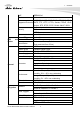
Table of Contents Table of Contents 1. Overview .....................................................................................................1 1.1 Introduction ..........................................................................................1 1.2 Features...............................................................................................2 1.3 Product Specification ...........................................................................2 1.4 System Requirement ................
Table of Contents 7.2 Exposure............................................................................................32 7.3 Image.................................................................................................34 7.4 WDR ..................................................................................................35 7.5 Overlay ..............................................................................................36 8. Audio...................................................
1. Overview 1 1. Overview This user’s guide explains how to operate this camera from a computer. User should read this manual completely and carefully before you operate the device. 1.1 Introduction AirLive BC-5010 / BC-5010-IVS is a standalone system that can be connected directly to an Ethernet or Fast Ethernet network. Equipped with a powerful 5 megapixel color CMOS sensor, the camera allows you to capture a wider field of view with high resolution up to 2592 x 1920. With supporting of latest H.
1. Overview 1.2 Features This manual will illustrate the steps of how to setup and operate this IP camera, so you’ll also soon be enjoying the benefits of these product features: 5 megapixel high resolution CMOS sensor 0.2Lux at F1.2 DC IRIS and IR-CUT Removable (ICR) Multiple Profiles Supported(H.
1. Overview Mechanical IR-Cut Yes Filter Auto Iris DC-Iris Support Viewing Angle Depend on lens Pan/Tile Control None Analog Video Out Yes Video Compression H.
1. Overview PoE Wireless IEEE802.3af Optional TCP/IP,IPV6, UDP, ICMP, DHCP, NTP, DNS, DDNS, Supported Protocols SMTP, FTP, HTTP, HTTPs, Samba, PPPoE, UPnP, Bonjour, RTP, RTSP, RTCP, DLNA, ONVIF, ISCSI Password protection Security IP filter HTTPS Users Up to 20 simultaneous users Power LED Amber Color LED and Link/Act.
1. Overview UPNP Application Programming Interface Video Buffer Alarm Events Continuous recording OS Viewing System DO (digital output) alarm SD/USB file upload Yes ONVIF 2.2 Open API for software integration SDK Pre- and post- alarm buffering File upload via FTP or email Notification via email, HTTP, and TCP External output activation Save to SD card/USB Yes Windows® XP, Vista, 7, 8 IE 7.0 or later, Firefox 2.
2. Package Contents and Installation 2 2. Package Contents and Installation 2.1 Package Content A user can find the following items in the package as below: 1. AirLive BC-5010/BC-5010-IVS is the main part of the product with Camera Mount Kit. Note: The lens is optional. For further information about the lens, please contact with your installer. 2. Power Adapter: DC 12V/1A 3.
2. Package Contents and Installation 2.2 Connections Front / Top / Side Panel 1. DC-iris Connector: It allows you to attach the DC-Iris lens (optional). 2. C and CS Lens Focus Ring: You can adjust C and CS lens focus ring to fit your lens type.
2. Package Contents and Installation 1. RJ45 LAN socket: Connect to PC or Hub/Switch. This Ethernet port built N-Way protocol can detect or negotiate the transmission speed of the network automatically. Please use Category 5 cable to connect the Network Camera to a 100Mbps Fast Ethernet network switch or hub. In the LAN socket, there are two LEDs below: LAN LED (green color) This LED will be flashing while network accessing via Ethernet.
2. Package Contents and Installation 6. SD Card Slot: SD Card Slot allows you to insert a memory card for expansion of storage. 7. USB Port: USB Port connects external USB device, such as flash drive or USB wireless adapter. 8. BNC connector: BNC connector can connect monitor to check camera focus and video quality. 9. Reset Button: This button is used to restore all the factory default settings. Sometimes restarting the device will make the system back to a normal state.
2. Package Contents and Installation 2. Connecting to LAN You can use the provided Ethernet cable to connect the camera to your local area network (LAN). When you connect the AC power adapter, the camera is powered on automatically. You can verify the power status from the Power LED on the Ethernet port. Once connected, the Link LED starts flashing green light and the camera is on standby and ready for use now.
2. Package Contents and Installation 3. Connect the external power supply to Camera Connect the attached power adapter to the DC power jack of the camera. Note: Use the 12VDC power adapter, included in the package, and connect it to wall outlet for AC power. Once you have installed the camera well and powered it on, the power LED (orange) will turn on later. When the power LED turned on, it means that the system is booting up successfully.
2. Package Contents and Installation C and CS Lens Focus Adjustment You can adjust C and CS lens focus ring to fit your lens type. 5. Applications of the Camera The camera can be applied in multiple applications, including: z Monitor local and remote places and objects via Internet or Intranet. z Capture still images and video clips remotely. z Upload images or send email messages with the still images attached.
2. Package Contents and Installation 2.4 Connect USB dongle for wireless function (Optional) You can add wireless function to your BC-5010 / 5010-IVS by connecting the optional wireless USB dongle. 2.5 Connect to IP Camera 1. Insert the bundle CD into your PC/Laptop. 2. Auto Run Screen then shows up; click “Install Software Æ “IP Wizard II” to install the configuration tool software.
2. Package Contents and Installation 3. After completing installation, run the configuration tool software. 4. The Software scans the network and finds the IP Camera and then lists them in the dialog box. 5. If the Camera’s IP address is in the same IP segment as your LAN, select the founded IP Camera and double click on the item. Then, the default browser will show up and connect to the IP camera’s Web automatically.
3. Using IP Camera via Web Browser 3 3. Using IP Camera via Web Browser 3.1 Windows Web Browser 1. Open your web browser, and enter the IP address or host name of the IP camera in the Location / Address field of your browser. Note: If you only want to view the video without accessing Setting screen, enter “http:///index2.htm” as your web URL. 2. Use the default account “admin” and default password “airlive”.
3. Using IP Camera via Web Browser 5. The monitor image will be displayed in your browser. In the left side of main configuration is “Configuration”. For more details, you can check the following chapters.
4. Operating IP Camera via Mobile Phone 4 4. Operating IP Camera via Mobile Phone 4.1 Using IP Camera via iPhone You can access into your IP camera via the iOS/Android device. Please follow the setup steps below. 1. Download AirLive CamPro Mobile 2. Execute the AirLive CamPro Mobile program. from APP store/Android market. 4. Setup page appears. 3. Click Setup button.
4. Operating IP Camera via Mobile Phone 5. Click Add button. 6. Click LAN button and select the camera.
5. Configuration of Main Menu 5 5. Configuration of Main Menu In the left side of main configuration is Configuration. For more details, please check the following Chapters. In the left side, you can control Live View in your main Browser. The functions include Function Buttons, Streaming Protocol, Video Profile, Monitor Image Section, Language and Digital Output.
5. Configuration of Main Menu 5.1 Live View 1. Function Buttons You can use the function buttons to control the camera’s audio, video, and zoom functions. z : Original screen to full Screen z : Full screen to original screen z : Enlarge the image of the camera digitally. z : Reduce the image of the camera digitally. z : Snapshot z : Record video z / : Click to mute/un-mute the microphone of the camera. When it is un-muted, you receive the on-site sound/voice where the camera is installed.
5. Configuration of Main Menu 6. Language The device can provide multiple languages to meet user’s requirement. 7. Digital Output This IPCAM allows you to trigger on/off the GPIO output manually. 5.2 Configuration This function is only for the Administrator. In the left side of main configuration, you can see Configuration including below.
5. Configuration of Main Menu Item Network Video Audio Event RS-485 System Status Action The Network menu contains the networking related settings for the camera, such as the IP Setting, DDNS Setting, IP Filter, etc. For more detail information, you can refer to Chapter 6. Configure bit rate and frame rate of video profiles, camera parameters, day & night. For more detail information, you can refer to Chapter 7. Configure audio parameters. For more detail information, you can refer to Chapter 8.
6. Configuration-Network 6 6. Configuration-Network Click the Network to display the sub-menus including General, UPnP/Bonjour/QoS, IP Filter, IP Notification, iSCSI.
6. Configuration-Network 6.1 General LAN Interface: This field allows you to select the IP address mode and set up the related configuration. The avail options include: DHCP IPv4, DHCP IPv4/IPv6, and Static IPv4/IPv6. - DHCP IPv4: Select this option when your network uses the DHCP server. When the camera starts up, it will be assigned an IP address from the DHCP server automatically. - DHCP IPv4/IPv6: DHCP for IPv6 enables the DHCP server to pass the configuration parameters (e.g.
6. Configuration-Network IP Address (IPv4/IPv6) Subnet Mask Default Gateway Primary/ Secondary DNS HTTP Port RTSP Port RTP Data Port Enter the IP address of the camera. The default setting is 192.168.1.100. Enter the Subnet Mask of the camera. The default setting is 255.255.255.0. Enter the Default Gateway of the camera. The default setting is 192.168.1.254 DNS (Domain Name System) translates domain names into IP addresses. Enter the Primary DNS and Secondary DNS that are provided by ISP.
6. Configuration-Network NOTE. Once the camera get an IP address from the ISP as starting up, it automatically sends a notification email to you. Therefore, when you select PPPoE as your connecting type, you have to set up the email or DDNS configuration in advance. Enable DDNS: Select this option to enable DDNS service of the camera. With the Dynamic DNS feature, you can assign a fixed host and domain name to a dynamic Internet IP address.
6. Configuration-Network 2. Bonjour: The devices with Bonjour will automatically broadcast their own services and listen for services being offered for the use of others. Select the Enable Discovery option and, if your browser with Bonjour, you can find the camera on your local network without knowing its IP address. The Apple Safari is already with Bonjour. You can download the complete Bonjour for Internet Explorer browser from Apple's web site by visiting http://www.apple.com/bonjour/. 3.
6. Configuration-Network 6.4 IP Notification In case the IP address is changed, system is able to send out an email to alert someone if the function is enabled. 1. Notification (e-mail): If enable this function, then the “Send to “and “Subject” fields need to be filled. - Send To: Type the receiver’s e-mail address. This address is used for reply mail. - Subject: Type the subject/title of the E-mail. 2.
6. Configuration-Network 3. HTTP Notification: If enable this function, then the fields below need to be filled. - URL: Type the server name or the IP address of the HTTP server. - HTTP Login name: Type the user name for the HTTP server. - HTTP Login Password: Type the password for the HTTP server. 6.5 iSCSI Enable the iSCSI and key-in server IP address and Port number. The disk of the server will be storage in IP cam setting. 6.
6.
7. Video Settings 7 7. Video Settings Click the Video to display the sub-menus including Video Profile, Exposure, Image, WDR, Overlay settings of the camera. .
7. Video Settings 7.1 Video Profile 1. ROI: ROI means Region of Interest. When the main stream is set to High Resolution, user can select specified region for monitoring, for this will saving the bandwidth if there are too many collision on the network. 2. Main Stream & Second Stream: To adjust the camera to capture images in several resolutions (up to 2592 x 1920 @ 15fps) in H.264, MPEG4, or MJEPG format.
7. Video Settings 2. Others - Modes: There are three modes (Indoor, Outdoor, and Auto) to fit your environment - Auto White Balance: You can enable or disable the function. - Auto Iris: When you attach a DC-Iris lens with the auto Iris function, select ON/OFF to enable/disable the feature. - IR-Cut: IR-Cut filter is used for the camera to produce true color images, which avoids the color deviation for the captured images effectively.
7. Video Settings 7.3 Image 1. Image Setting - Brightness: Adjust the brightness level from 0~255. - Contrast: Adjust the contrast level from 0~255. - Saturation: Adjust the colors level from 0~255. - Sharpness: Adjust the sharpness level from 0 ~ 100. TIP: Click Default to restore the default settings of the three options above. 2. Others - Mirror: Select Vertical to mirror the image vertically, or select Horizontal to mirror the image horizontally.
7. Video Settings 7.4 WDR 1. WDR Setting You can adjust WDR level to fix your backlight environment. 2. BLC Setting You can adjust BLC level to fix your backlight environment.
7. Video Settings 7.5 Overlay This option is used to set the image overlay and mask feature of the camera. 1. Overlay Setting - Enable Time Stamp: Select this option to display the date & time information on the live view image. - Enable Text Display: Select this option and enter your heading text in the box to display the text information on the live view image. You can set the displayed text in transparent mode by selecting the Transparent option.
8. Audio 8 8. Audio Click the Audio to display the sub-menus including Audio Setting. 8.1 Audio Setting 1. Microphone: Select the option to enable the camera’s audio in function, so that you can receive the on-site sound and voice from the camera. 2. Speaker: Select the option to enable the camera’s audio out function, so that the connected speaker can play the sound and voice through the camera. 3. Recording File: You can upload audio file for event action.
9. Event 9 9. Event Click the Event to display the sub-menus including Event, Event Schedule, Motion Detection and Tamper Detection. 9.1 Event 1. Media Format: Select One Snapshot to send the alert message with one still image captured by the camera, or select H264 Video to send the alert message with one video clip recorded by the camera. You can set the attachment that is captured in Pre Event or Post Event time when the event has been triggered. 2.
9. Event - User Name: Enter the user name to login into the FTP server. - Password: Enter the password to login into the FTP server. - File Path Name: Enter the destination folder for uploading the images. For example, /Test/. - Enable Passive Mode: Select the Enable option to enable passive mode. - Test FTP: When done, click the button to test the FTP server. NOTE. Due to the network environment, the camera may not upload number of images that you set. 3.
9. Event NOTE. Due to the network environment, the camera may not upload number of images that you set. 9.2 Event Schedule This menu is used to specify the schedule of Event or Schedule Trigger and activate the some actions provided by this device. Where the Schedule Trigger will be activated by user-define interval without event happened. Follow the steps below to set up the Event Schedule for the camera: 5. Select Enable and enter the Event Name. 6.
9. Event 9.3 Motion Detection The Motion Detection option contains the commands and settings that allow you to enable and set up the motion detection feature of the camera. The camera provides three detecting areas. Follow the steps below to set up the Motion Detection function for the camera: 1. Select Enable Motion Detection. 2. Select Window 1/2/3. When the detecting area is enabled, you can use the mouse to move the detecting area and change the area coverage. 3.
9. Event 9.4 Tamper Detection Tamper Detection allows the events triggered by scene change / bright images / dark images / movement images / blur images.
10. RS-485 10 10. RS-485 Click the RS-485 to display the sub-menus including RS-485 Settings, RS-485 PTZ.
10. RS-485 10.1 RS-485 Settings The RS-485 option provides the control settings for external device through the I/O port. Select Enable RS-485 and complete the required settings to activate the RS-485 function of the camera. Use Pelco-D: Select this option and then select an Address. When you enable the RS-485 function of the camera, you will be able to use the RS-485 Buttons on the live view screen to control the camera. Use Custom Protocol: Select this option to configure the commands protocol manually.
11. System 11 11. System Click the System to display the sub-menus including Device Settings, Account, Management Ports, Firmware, Maintenance.
11. System 11.1 Device Settings Use this menu to perform the principal settings of the device. 1. DIPS - DIPS (Dynamic IP Service): To enable or disable the DIPS® (Dynamic IP Service) function. - Device ID (for DIPS): It’s a unique number of each device for identification and this ID is used for DIPS. This function now is reserved for future use. 2. Information: The information of Camera Name and Location. 3. Indication LED: This item allows you to set the LED illumination as desired.
11. System 2. Users - User Name/Password/Confirm Password: Enter the user’s name you want to add to use the camera. Then, enter the password twice for the new user. When done, click Add to add the new user for the camera. - User List: Display the existing users of the camera. To delete a user, select the one you want to delete and click Delete. 3. Guest - User Name/Password/Confirm Password: Enter the user’s name you want to add to use the camera. Then, enter the password twice for the new user.
11. System 11.3 Management Ports 1. HTTP: To define HTTP Ports. The default HTTP port is 80 2. HTTPS: Select the Enable HTTPS option to enable HTTPS, which is a secure protocol to provide authenticated and encrypted communication within your network. - HTTPS Port: Assign a HTTPS port in the text box. The default HTTPS port is 443. 11.4 Firmware 1. Update Firmware: You can upgrade the firmware for your camera once you obtained a latest version of firmware.
11. System 11.5 Maintenance 1. Factory Reset: Click Reset to restore all factory default settings for the camera. 2. System Rebooted: Click Reboot to restart the camera just like turning the device off and on. The camera configuration will be retained after rebooting. 3. Configuration Backup/Restore: You can save your camera configuration as a backup file on your computer. Whenever you want to resume the original settings, you can restore them by retrieving the backup file.
12. Status 12 12. Status Click the Status to display the sub-menus including Basic, Audio/Video, Network, System Log. 12.1 Basic Basic information includes Camera Name, Firmware version, MAC, Camera Date & Time. 12.2 Audio/Video 1. Video -H.264: Video Resolution/Video Quality/Frame Rate -MJPEG: Video Resolution/Video Quality/Frame Rate -Mobile View: 3GPP (Enable/Disable) 2.
12. Status 12.3 Network 1. Wired Interface IP Mode IP Address (IPv4/IPv6) Subnet Mask Gateway Primary/ Secondary DNS MAC 2. Wireless Interface Status IP Address Subnet Mask Gateway MAC DHCP or Static IP address of the camera. The default setting is 192.168.1.100. Subnet Mask of the camera. The default setting is 255.255.255.0. Gateway of the camera. The default setting is 192.168.1.254 DNS (Domain Name System) translates domain names into IP addresses.
12. Status 12.4 System Log You can check the usage log of IP camera here. In this page, you can click: 1. First page / Final page: Jump to first / final page of log. 2. Previous / Next: Jump to previous or next page of log. 3. Remove: Clear log.
13. Video Analytics 13 13. Video Analytics 13.1 Video Analytics (Only for BC-5010-IVS) BC-5010-IVS provides multiple intelligent video analytics that helps you to save your human resources and reach the goal of automatic surveillance. Please go to ConfigurationÆVideo Analytics to experience the entire IVS function. Note: Only one Video Analytics function can be excuted at same time. When using Video Analytics,we will recommend you to use 2-Megapixel resolution for best performance.
13. Video Analytics z Sensitivity: Adjust sensitivity 0~100%, the higher sensitivity means more precisely and detailed face detection. z Event Conditions: Once you want to change the trigger condition, you have to select the event interval by NONE, Daily, Hourly or User Define and Quantity. For example, if you set Interval with NONE, no matter how many triggers you select, the alarm will be on when IP Camera detect the face. z Set Event Action: Go to the Event Schedule to Add or Edit the IVS event.
13. Video Analytics z Statistics Record: This function can record how many faces have been detected. You can configure your camera in different ways to generate the statistics you required and statistic data can be exported in csv format file. - Select Statistics Period to specify the period you want the data for. - Select the range to export the data or press “Reset” to delete it. z Statistics Chart Display: Enable this to see the detection result by chart. 2.
13. Video Analytics z Edit Users Database: You can edit the registered database here. (See below) 3. iMotion Detection (Intelligent Motion Detection) Intelligent Motion Detection is able to increase the accuracy of motion detection and also provides more flexible setting with polygon for the zones. Any moving object in the zone will trigger this alarm. Objects must move and stay within the boundary for at least 100 ms. z Select Sensitivity to set the detection sensitivity level.
13. Video Analytics z Select Calibration (People or Vehicle Object Sizes).The minimum and maximum boundary of objects can be specified to improve the detection accuracy. The width and length values must be at least 6 pixels. If any false detection caused by smaller objects, you can try to increase the minimum size. ‐ Min. Size of Calibration: The width and length values must be 6 pixels at least. If any false detection caused by smaller objects, you can try to increase the minimum size. ‐ Max.
13. Video Analytics z Select Calibration (People or Vehicle Object Sizes).The minimum and maximum boundary of objects can be specified to improve the detection accuracy. If any false detection caused by smaller objects, you can try to increase the minimum size. z In Event Conditions, you can specify the minimum time interval and quantity (500 at most) for each alarm. And go add or edit the IVS event in the Set Event Action. z Select Rotate Mode or Transform Mode in Edit Mode.
13. Video Analytics z z z z z z z ‐ ‐ z z ‐ ‐ Select Sensitivity to set the detection sensitivity level. Higher sensitivity will make it easier to detect and less objects missing, but more misjudgments. Select People / Vehicles / Anything as the detected objects. Select Calibration (People or Vehicle Object Sizes).The minimum and maximum boundary of objects can be specified to improve the detection accuracy. If any false detection caused by smaller objects, you can try to increase the minimum size. –Min.
13. Video Analytics z Select Sensitivity to set the detection sensitivity level. Higher sensitivity will make it easier to detect and less objects missing, but more misjudgments. z Select People / Vehicles / Anything as the detected objects. z Select Calibration (People or Vehicle Object Sizes).The minimum and maximum boundary of objects can be specified to improve the detection accuracy. The width and length values must be at least 6 pixels.
14. Appendix 14 14. Appendix A. Alarm I/O Connector Some features of the Camera can be activated by the external sensor that senses physical changes in the area Camera is monitoring. These changes can include intrusion detection or certain physical change in the monitored area. For examples, the external sensor can be a door switch or an infrared motion detector. These devices are customer provided, and are available from dealers who carry surveillance and security products.
14. Appendix Explanation of External I/O Circuit Diagram: CAUTION! • THE LOW VOLTAGE/CURRENT CIRCUITS AND HIGH VOLTAGE/ CURRENT CIRCUITS ARE IN THE NETWORK CAMERA CIRCUIT. THE QUALIFIED ELECTRICIAN SHOULD DO THE WIRING NOT BY YOURSELF. INCORRECT WIRING COULD DAMAGE NWTWORK CAMERA. YOU COULD RECEIVE THE FATAL ELECTRIC SHOCK. • THE EXTERNAL I/O IS NOT CAPABLE OF CONNECTING DIRECTLY TO DEVICES THAT REQUIRE LARGE AMOUNTS OF CURRENT.