FE-200CU 2-MegaPixel Wall Mount Fish Eye PoE IPCAM User’s Manual 1 AirLive FE-200CU Manual
Copyright and Disclaimer Owner's Record The model and serial numbers are located at the bottom of device. Record these numbers in the spaces provided below. Refer to these numbers whenever you call upon your dealer regarding this product. Model No. ____________________ Serial No. ____________________ To prevent fire or shock hazard, do not expose the unit to rain or moisture. For AC Adaptor to avoid electrical shock, do not open the cabinet. Refer servicing to qualified personnel only.
Copyright and Disclaimer Notice: The changes or modifications not expressly approved by the party responsible for compliance could void the user’s authority to operate the equipment. For customers in the U.S.A. This equipment has been tested and found to comply with the limits for a digital device, pursuant to Part 15 of the FCC Rules. These limits are designed to provide reasonable protection against harmful interference in a residential installation.
Copyright and Disclaimer IMPORTANT NOTE: To comply with the FCC RF exposure compliance requirements, no change to the antenna or the device is permitted. Any change to the antenna or the device could result in the device exceeding the RF exposure requirements and void user’s authority to operate the device. NOTICE TO USERS © 2006~11 All rights reserved.
Table of Contents Table of Contents 1. Introduction.................................................................................................................1 1.1 Overview..............................................................................................................1 1.2 Package Contents ...............................................................................................2 1.3 Physical Overview and Connections..................................................................
Table of Contents 4.4 Schedule............................................................................................................32 4.4.1 General....................................................................................................32 4.4.2 Storage ....................................................................................................32 4.5 Network .............................................................................................................33 4.5.
1. Introduction 1 1. Introduction 1.1 Overview AirLive FE-200CU is a Fish-Eye Network Camera; it is featured with superior H.264-AVC performance and rich functions. AirLive FE-200CU includes a fish-eye lens for 360° wide angle view without blind spot. Thus, AirLive FE-200CU is very suitable to view a wide area with only one single camera such as hallway, store, office, and etc. The H.264-AVC video compression enables to lower bandwidth and storage requirements without compromising image quality.
1. Introduction The e-PTZ function including preset point without moving parts, can replace part of traditional PTZ camera and thus save lots of cost for maintaining traditional mechanical Pan/Tilt. The camera offers optional PoE type for installation. The PoE (IEEE802.03af) feature provides an easy installation through a single Ethernet cable, which lessens the installation of power plugs or extensions. Further functions include two-way audio and micro SD card for local storage application.
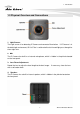
1. Introduction 1.3 Physical Overview and Connections 1. Light Sensor: The Light sensor is for detecting IP Camera environmental illumination. If IP Camera is in the dark/night environment, IR Cut Filter is switched off to let infrared light pass through for clear night view. 2. MIC: The IP Camera has built-in an internal microphone, which is hidden in the pinhole located on the front panel. 3. Lens Focus Adjustment: Rotate the lens to adjust the focal length to the best image. with a soft cotton cloth.
1. Introduction 5. Reset Button The Reset Button is located on the back panel. To restore to the factory default, please follow the steps: (1.) Unplug the power jack to turn off the power of the camera. (2.) Insert a pin into the reset hole. Sense a button and keep it pressed until instructed to release. (3.) Plug in the power jack to turn on device, and the status LED will be quick flashing after a few minutes. (4.) Release the button (remove the pin from the reset hole).
1. Introduction 9. Micro SD Card slot: The IP Camera has built-in a Micro SD card slot which can accepts Micro SD memory card for image / video event recording. 1.4 Mounting the Camera 1. Take out the camera and accessories from the package: The stand and FE-200CU 2. First, pass the network cable through the hole of the stand, then fasten the screws with stand into the wall.
1. Introduction 3. Install the FE-200CU onto the stand, and connect the network cable. 4. You can adjust the silver screw to fix the angle of camera.
1. Introduction 1.5 Install the Camera in LAN 1. Plug an Ethernet cable into the Camera Connect an Ethernet cable to the LAN socket and attach it into the network. 2. Connect the external power supply to Camera Connect the attached power adapter to the DC power jack of the camera. Note: Use the power adapter, 12VDC, included in the package and connect it to wall outlet for AC power. Once you have installed the camera well and powered it on, the power LED (orange) will turn on later.
2. Preparation 2 2. Preparation 2.1 Search and Set up by IPWizard II When you install the Camera on a LAN environment, you have two easy ways to search your Camera by IPWizard II or UPnP™ discovery. Here is the way to execute IPWizard II to discover Camera’s IP address and set up related parameter in a Camera. 2.1.1 Search When launch the IPWizard II, a searching window will pop up. IPWizard II is starting to search Network Cameras on the LAN. The existed devices will be listed as below.
2. Preparation 2.2 UPnP of Windows® XP, Vista or 7 UPnP™ is short for Universal Plug and Play, which is a networking architecture that provides compatibility among networking equipment, software, and peripherals. This device is an UPnP enabled device. If the operating system, Windows XP, Vista or 7, of your PC is UPnP enabled, the Network Camera will be very easy to be found. Please refer to Appendix J to enable UPnP settings only if your operating system of PC is running Windows XP.
2. Preparation Click the targeted Device. Then Internet Explorer will connect to this Network Camera automatically. 2.3 Install the Device behind a NAT Router Once installed, the device is accessible on your LAN. To access the device from the Internet, you must configure your broadband router to allow incoming data traffic to the device. If the device is installed on the LAN with a router, then it may get a dynamic IP address from the DHCP server.
2. Preparation (2) Enable UPnP NAT traversal option of the Network Camera Refer to Setting Î Network Î UPnP page for detail NAT traversal setting. Note that this option is default enabled. (3) Access your Network Camera by DIPS Refer to Setting Î System Î System page for detail DIPS information. 2.4 Access the Device from the Internet Explorer for the First Time 1.
2. Preparation 3. According your browser’s security setting, the IE Web Page may prompt the “Security Warning” window. If so, select “Yes” to install and run the ActiveX control into your PC. Otherwise, the system will load the ActiveX silently. 4. After the ActiveX control is installed and ran, the first image will be displayed. 2.5 Logging in as an User If you log in the Camera as an ordinary User, “Configuration” function will be not accessible. 2.
3. Operating the Network Camera 3 3. Operating the Network Camera Start-up screen will be as follow no matter an ordinary users or an administrator. Configuration Click for configuring the camera settings. Language The device can provide multiple languages to meet customer’s requirement. Display Mode Click on different video modes to display different views. Actual Size Display the actual resolution size of the video when checked. Video Profile The device supports multi-profile function for H.
3. Operating the Network Camera Protocol A user can select proper streaming protocol according to network environment. Manual Trigger Trigger manually a preset event in the configuration page. PTZ The PTZ function will display in Broad view, Quad view, Quad with source view, Double view and Triple view of Ceiling Mount. Click on the PTZ icon, the web will popup the control panel to control e-PTZ function of FE-200CU. z Broad view PTZ control panel: 1. Step: Set the speed of Pan Function. (1~10) 2.
3. Operating the Network Camera z Quad view & Quad with source view PTZ control panel: 1. Ch:Select the channel. (1~4) & (2~4) 2. Step:Set the speed of Pan/Tilt Function. (1~10) 3. Pan/Tilt Arrow:Click to control the Pan/Tilt Function. 4. Zoom:Digital zoom in/out. (1~10) 5. Move the control panel. 6. Close the control panel. 7. List of preset points. (1~16) 2-Way Audio The device supports 2-way audio function. A user can choose to enable or disable this function by toggling the icon below.
3. Operating the Network Camera Volume Click Speaker button to activate this function. Scroll the control bars to adjust the audio attribute. Full Screen Enlarge video to full screen display. Press “ESC” key to disable this function. Snapshot Click Snapshot to activate this function. Press Snapshot button to take a picture. The image file is saved as JPEG format into your local PC.
4. Administrating the Device 4 4. Administrating the Device System Setting This function is only available for a user logs into Camera as administrator. Click on each menu name to display its setting page. Item Action Video Configure bit rate and frame rate of video profiles. Camera Adjust camera parameters. Event Setup Event server, Motion Detection, I/O Ports and Event configuration.
4. Administrating the Device 4.1.2 Advanced z Stream Setting Note: Configuration of stream 2 is the same as stream 1, but Stream 2 can only be set to 320x240 or 640x480. z RTSP Path The RTSP Path is the stream ID used for RTSP client streaming connection, such as VLC player. The default values are v00, v01 and v02 for the three streams respectively. The string can be any combination of number or capital/small letters. It cannot be empty however.
4. Administrating the Device z Image Format H.264 and MJPEG are available for image format selection. The term, “image format”, is referring to compression / encoding technique. The selection of image format decides the performance of bandwidth and storage requirement. In the request of same video quality, H.264 contributes to less bandwidth and storage requirement, which is more efficient than MJPEG. z GOP In H.
4. Administrating the Device 4.2 Camera: Adjust Camera Parameters Use this menu to set the functions of the camera parameters of the device. 4.2.1 General Use this function to determine the Auto Contrast Compensation level. z Camera General Setting: Brightness: Set the luminance of image. Hue: Refer to pure color; it modifies the different display of specific color such as red, green or blue. Saturation: Set the intensity of a specific color.
4. Administrating the Device z Audio Setting: Audio Enable: Turn on/off the audio. z Web Record Setting: Save Path / File name: Click on the “Browse” button to select the desired path to save as well as naming the video file. z Web Snapshot Image Setting: Save Path / File name: Click on the “Browse” button to select the desired path to save the snapshot as well as naming it. z Save: Save the changes that have been made.
4. Administrating the Device 4.2.2 Advanced z White balance: Adjustment to compensate for different environments in terms of light source. A user can choose auto/hold/sunny/cloudy /indoor, so FE-200CU can determine the correct color compensation due to different light environment. z Exposure: Anti-flicker setting for image sensor to fit the frequency of light (power) source. For instance, the power frequency is 50Hz for most European countries, while 60Hz is typically for US.
4. Administrating the Device z Infrared (IR) Cut Filter: The default is automatically switched according to the light intensity. “Enable” indicates the filter is enable to cut IR light to make sure the color is correct. “Disable” indicates the filter is disabled and allows the infrared (such as IR LED illuminator) to enter the camera to execute low lux surveillance application. z Day / Night Threshold: The threshold to change Day or Night mode. The default is 20 lux.
4. Administrating the Device (3) Quad with source view: (4) Triple view: 2. Ceiling Mount: For Choosing Ceiling mount, go back to live view. There are 6 kinds of video layout to choose from Original view, Broad view, Quad view, Quad with source view, Double view and Triple view. (1.
4. Administrating the Device (2.) Broad view: (3.) Quad view: (4.) Quad with source view: (5.
4. Administrating the Device (6.) Triple view: 3. 720P Wall Mount: For Choosing 720P Wall Mount type, go back to Live view. There are 3 kinds of video layout to choose, including Broad view、Double view、Double with source view. (1.) Broad view: (2.) Double view: (3.
4. Administrating the Device 4.3 Event 4.3.1 Event Server z Add FTP Server: Click on the “Add FTP” to expand FTP server setting. FTP Server: Name: Give a name for the FTP server Network Address: Input the network address of the FTP server Upload Path: Choose the desired upload path for events Port: Input the port number of the FTP server Login Information: Username / Password: Input the username and password of the FTP z Add HTTP Server: Click on the “Add HTTP” to expand HTTP server setting.
4. Administrating the Device HTTP Server: Name: Give a name for the HTTP server URL: Input the network address of the HTTP server Username / Password: Input the username and password of the HTTP. z Remove: Click “Remove” to delete selected event servers.
4. Administrating the Device 4.3.2 Motion Detection z To add a motion detection area: 1. Click on “Add” to set up a detection area. (Setup panel will be expanded) 2. Give a name to this window area. 3. Select the trigger level and sensitivity for this detection window. (0~100, low~high) 4. Select color for detection window.
4. Administrating the Device 5. Draw detection window on the image. 6. Once everything is done, click on “Save” to save the configuration made. Configured detection window will be displayed in motion detection list. (Circled in blue) Note: 1. Maximum number of detection window is 10. 2. Motion Detection windows need to be modified if users change video layout.
4. Administrating the Device 4.3.3 I/O Ports AirLive FE-200CU supports 1 photo-coupled relay inputs and 1 relay outputs. Refer to “Appendix A: I/O Terminal Connectors” for detail pin description and application. The below table shows the status of the external trigger/alarm devices. 4.3.4 Event Configuration 1. To add an event trigger, click on “Add” and the setup panel will be expanded. 2. Give a name to this event. 3. Set the time interval between each trigger. 4. Set the time period for the trigger.
4. Administrating the Device 5. The trigger condition is Motion Detection. The responding actions can be “Upload images” and “Activate Output Port” and “Send Email Notification” and “Send HTTP Notification to” and “Send Message Notification (TCP)”. Click on “Save” to save the configuration made. 4.4 Schedule 4.4.1 General Define the day (specified by days of a week) and time (specified by each single hour) for that will be recorded during the scheduled period. Note only video data will be recorded.
4. Administrating the Device 4.5 Network 4.5.1 General Device IP configuration, includes DHCP and Static IP setting. “Enable ARP/Ping” enables device to accept ARP or ping packets from the network. Disabling this option may provide extra security from intentional ping. z DHCP Service: Stand for Dynamic Host Configuration Protocol.
4. Administrating the Device Enable this checked box when a DHCP server is installed on the network to issue IP address assignment. With this setting, the IP address is assigned automatically. If this device can not get an IP address within limited tries, the device will assign to the default IP address, 192.168.1.100, by itself. z IP address, Subnet mask, and Gateway: If you do not select Obtain an IP address automatically, then you need to enter these network parameters manually.
4. Administrating the Device 4.5.2 Advanced Enable or configure other network functions. z z z z z NTP: Configure a NTP (Network Time Protocol) server, so that the device system date and time can be synchronized with a specified Time Server or DHCP server. HTTP: Set the HTTP port that will be applied for Web UI access. RTSP: Set the RTSP (Video) port for video data transmission. UPnP: Enable UPnP, so that the device can be discovered in an UPnP Compliant Network.
4. Administrating the Device 4.5.4 DDNS (Dynamic DNS) Dynamic DNS configuration. The network device can be assigned with a host name by registering this service (Internet access required). z Host Name: Assigned name that will be used for access to the device z User Name/Password: Account authentication for logging to this service. z Update Time: Periodically, the device updates its access info to sever in the configured time. z Response: The device responds the connection info.
4. Administrating the Device 4.6 System 4.6.1 Information Lists - System and Network configurations. z Firmware Version: This information shows the firmware version of the device. 4.6.2 User Use this menu to add, update, or remove the usernames and passwords of the Administrator and viewer. Note: For configuration settings, an Administrator username and password is still required.
4. Administrating the Device The default username and password is admin/admin respectively. 4.6.3 Day & Time You can setup the device or make it synchronized with PC or remote NTP server. Also, you may select your time zone in order to synchronize time locally. z z z z z Current Server Time: Displaying the date and time of the device. Synchronize with computer time: Click this option to enable time synchronization with computer time.
4. Administrating the Device z Reboot: The device is restarted without changing any of the network settings. I t means the IP address of the device will not change after firmware upgrade. z Load Default (Excluding Network setting): The unit is restarted and most current settings are reset to factory default values. This action will not reset the network setting. z Factory Default (Including Network setting): Recall the device hard factory default settings.
4. Administrating the Device 1. Close all other application programs which are not necessary for firmware update. 2. Make sure that only you access this device while firmware updating. 3. Disable Motion Detection function. 4. Click “Browse” button. Select the Firmware binary file. (Note that it must make sure that the Firmware only applies to this device, once update, it will be burned into FLASH ROM of system.) 5. Once the firmware file was selected, click “Firmware Upgrade” button. 6.
4. Administrating the Device 4.6.5 Log Service Most system operations and / or process will be kept in a log system. The link provides the review of these records. 4.7 Customize This page provides the user features to customize the outlook of the web user interface There are two types of layout settings: Use Default Look or Use Custom Settings. z Use Default Look: The default layout of live/configuration pages. Use Defined Links: Web link(s) will be presented on the live page when enabled.
4. Administrating the Device z Use Custom Settings: The allowed modifications are changing of Background / Text Color, Background picture, Title, Description, Logo Link and Logo.
5. Appendix 5 5. Appendix Appendix A: Alarm I/O Connector This Network Camera provides a general I/O terminal block as below: Pin 1 2 3 4 5 6 Function COM RELAY-NO Description Digital output implementation; Pin2 to COM (Pin1) is a Photo-coupled relay on Normal Open status. External device can directly connect to the terminals. However the current that will go through the 2 nodes must not exceed 130mA. An external “Relay” can also be connected to the terminals as an implementation.
5. Appendix Appendix B: Troubleshooting & Frequently Asked Questions Question Answer or Resolution Features The video and audio codec is adopted in the device. The maximum number of users accesses the device simultaneously. The device can be used outdoors or not. Status LED does not light up. The network cabling is required for the device. The device will be installed and work if a firewall exists on the network. The device utilizes H.
5. Appendix The username and password for the first time or after factory default reset Forgot the username and password Forgot the IP address of the device. IPWizard II program cannot find the device. Internet Explorer does not seem to work well with the device IPWizard II program fails to save the network parameters. Username = admin and Password = airlive. Note that it’s all case sensitivity. To restore factory default, please follow the steps: 1.
5. Appendix UPnP NAT Traversal Can not work with NAT • Maybe NAT router does not support UPnP function. router Please check user’s manual of router and turn on UPnP function. • Maybe UPnP function of NAT router is not compatible to the IP camera. Please contact your dealer to get the approval routers list. Some IP cameras are Maybe too many IP cameras have been installed on the working but others are LAN, and then NAT router is out of resource to support failed more cameras.
5. Appendix Image or video does not appear in the main page. Check the device’s ActiveX is installed on your computer • Confirm that Default Gateway address is correct. • The router needs Port Forwarding feature. Refer to your router's manual for details. • Packet Filtering of the router may prohibit access from an external network. Refer to your router's manual for details. • Access the Network Camera from the Internet with the global IP address of the router and port number of Network Camera.
5. Appendix Internet Explorer displays the following message: “Your current security settings prohibit downloading ActiveX controls”. The device work locally but not externally. Setup the IE security settings or configure the individual settings to allow downloading and scripting of ActiveX controls. • Might be caused from the firewall protection. Check the Internet firewall with your system or network administrator.
5. Appendix • If FTP does not work properly, ask your ISP or network administrator about the transferring mode of FTP server. Pan/Tilt does not work. • Click [Refresh] on the Internet Explorer when the (including Click to communication stops with the device. The image will Center and Preset refresh. Positioning) • Other clients may be operating Pan/Tilt. • Pan/Tilt operation has reached the end of corner. Pan/Tilt does not work There may be a slight delay when you are using the smoothly.
5. Appendix Appendix C: PING IP Address The PING (stands for Packet Internet Groper) command is used to detect whether a specific IP address is accessible by sending a packet to the specific address and waiting for a reply. It’s also a very useful tool to confirm the device installed or if the IP address conflicts with any other devices over the network. If you want to make sure the IP address of the device, utilize the PING command as follows: z Start a DOS window. z Type ping x.x.x.x, where x.x.x.
5. Appendix Actual results generated by the device may be varying. Image Resolution 160 x 120 (QQVGA) 320 x 240 (QVGA) 640 x 480 (VGA) 1280x1024 (SXGA) Average range of data sizes for JPEG mode 3 ~ 6k byte per frame 8 ~ 20k byte per frame 20 ~ 50K byte per frame 100 ~ 200k byte per frame Average bit rate for MPEG4 mode Average bit rate for H.
5.
5. Appendix Software Search & Installation Bundled NVR Program IPWizard II CamPro Express 64, CamPro Professional Appendix F: Configure Port Forwarding Manually The device can be used with a router. If the device wants to be accessed from the WAN, its IP address needs to be setup as fixed IP address, also the port forwarding or Virtual Server function of router needs to be setup. This device supports UPnP traversal function.
5. Appendix you restart your computer. Your WAN IP Address will be listed here. Note: Because a dynamic WAN IP can change from time to time depending on your ISP, you may want to obtain a Static IP address from your ISP. A Static IP address is a fixed IP address that will not change over time and will be more convenient for you to use to access your camera from a remote location. If you could not get a Static IP address from your ISP, the DIPS™ or DDNS is a solution alternatively.
5. Appendix • Enter your camera’s local IP Address (e.g., 192.168.0.100, for example) in the Private IP field. • If you are using the default camera port settings, enter 80 into the Public and Private Port section, click Apply. • Scheduling should be set to Always so that the camera images can be accessed at any time. A check mark appearing before the entry name will indicate that the ports are enabled. Important: Some ISPs block access to port 80.
5. Appendix Appendix G: DDNS Application z Preface If you have a Cable modem or xDSL, this is a great way to host your own Networked Device or other TCP/IP Service. Get your own domain like www.yourname.com, www.yourname.com.tw etc. (Note: This domain must be registered with Internic via registration authorities such as Network Solutions, DirectNIC, Register.com etc). Your domain name's dynamic IP address is automatically tracked by a DDNS server.
5. Appendix (3). After the columns show up at the left side, click “Create Account”. (4). Fill the application agreement and necessary information. a. Username b. E-mail address and confirmation c. Password and confirmation d.
5. Appendix Click these two options (5). Check your e-mail mailbox. There will be an e-mail with a title “Your DynDNS Account Information“. Click the hyperlink address to confirm the DDNS service that you just applied. Then DDNS you applied activated.
5. Appendix Click to confirm (6). Enter the web page http://www.dyndns.org/ again. Input your username and password that you just applied to login administration interface of DDNS server. Input your account (7). If the correct username and password are input, you can see the following picture at the top-right of the login page.
5. Appendix (8). Click the “Services”. (9). Click the “Dynamic DNS”. (10). Click the “Get Started”.
5. Appendix (11). We could create a domain name without any charge at this step. First, we input the host name. (Pink No.1) Then we pick a domain that is easy to remember. (Pink No.2) The 3rd step is to click “Offline Hostname” from Service Type. (Pink No.3) Finally, click the “Create Host” to submit the domain name information and finish DDNS application. (Pink No.
5. Appendix Appendix H: Power Line Frequency COUNTRY Argentina VOLTAGE FREQUENCY COMMENTS 220V 50 Hz *Neutral and line wires are reversed from that used in Australia and elsewhere. *Outlets typically controlled by adjacent switch. Though nominal voltage has been officially changed to 230V, 240V is within tolerances and commonly found.
5. Appendix Portugal 230V 50 Hz Spain 230V 50 Hz Sweden 230V 50 Hz Switzerland 230V 50 Hz Taiwan 110V 60 Hz Thailand 220V 50 Hz United Kingdom 230V* 50 Hz United States of America 120V 60 Hz *Outlets typically controlled by adjacent switch. Though nominal voltage has been officially changed to 230V, 240V is within tolerances and commonly found.
5. Appendix Appendix J: Enable UPnP of Windows XP Use the following steps to enable UPnP settings only if your operating system of PC is running Windows XP. Go to Start > Settings.
5.
5.
5. Appendix Please wait while Setup configures the components.