SNMP-GSH2404L 24+4 Gigabit SNMP Lite Switch User’s Manual
Copyright and Disclaimer Copyright & Disclaimer No part of this publication may be reproduced in any form or by any means, whether electronic, mechanical, photocopying, or recording without the written consent of OvisLink Corp. OvisLink Corp. has made the best effort to ensure the accuracy of the information in this user’s guide. However, we are not liable for the inaccuracies or errors in this guide. Please use with caution.
Copyright and Disclaimer Federal Communications Commission (FCC) Statement This equipment has been tested and found to comply with the limits for a class A computing device pursuant to Subpart J of part 15 of FCC Rules, which are designed to provide reasonable protection against such interference when operated in a commercial environment.
Table of Contents Table of Contents 1. Introduction ................................................................................................1 1.1 Overview ..............................................................................................1 1.2 How to Use This Guide ........................................................................1 1.3 Firmware Upgrade and Tech Support ..................................................2 1.4 Features..................................................
Table of Contents 4.2.10 Mirror Configuration .................................................................................40 4.2.11 QoS Configuration ...................................................................................41 4.2.12 Filter.........................................................................................................44 4.2.13 Rate Limit ................................................................................................46 4.2.14 Storm Control............
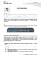
1. Introduction 1 1. Introduction 1.1 Overview The SNMP-GSH2404L is a 24-port Gigabit Lite SNMP Managed Switch with 20-Port Gigabit TP slots and 4-Port Gigabit TP/SFP slots. This Switch can be used to build high-performance switched workgroup networks. The switch can be managed through web browser and SNMP agent.
1. Introduction 3.4 Introduction to Web Management: This section tells you how to get into the WebUI using HTTP. Chapter 4: This chapter explains all of the management functions via Web management. Chapter 5: If any trouble in using SNMP-GSH2404L, you can refer to this chapter Chapter 6: This chapter shows technical specification of SNMP-GSH2404L. Chapter 7: Explanation on network technical terms from A to Z. Highly recommended for reference when you encounter an unfamiliar term. 1.
1. Introduction 1.4 Features Confirms to IEEE802.3 10BASE-T, 802.3u 100BASE-TX, 802.3ab 1000BASE-T, 802.3z Gigabit fiber 20 x 10/100/1000Mbps Auto-negotiation Gigabit Ethernet TP ports and 4x 10/100/1000Mbps TP or 1000Mbps SFP Fiber dual media auto sense High back-plane bandwidth 48Gbps 8K MAC address and support VLAN ID (1~4094) Power Saving with "ActiPHY Power Management" and "PerfectReach Power Management" techniques.
2. Installing the SNMP-GSH2404L 2 2. Installing the SNMP-GSH2404L This chapter describes the hardware features and the hardware installation procedure for the SNMP-GSH2404L. For software configuration, please go to chapter 3 for more details. 2.2 Before You Start It is important to read through this section before you install the SNMP-GSH2404L. The maximum cabling distance is 100 meters. Do not create a network loop. Always check the LED lights for troubleshooting 2.
2. Installing the SNMP-GSH2404L RS-232 cable User Guide (CD-ROM) Quick Installation Guide Rack-mounted Kit Compare the contents of your SNMP-GSH2404L package with the standard checklist above. If any item is missing or damaged, please contact your local dealer for service. 2.
2. Installing the SNMP-GSH2404L 2.5 Knowing your SNMP-GSH2404L Below are descriptions and diagrams of the product: 2.6 Hardware Installation Set the SNMP-GSH2404L on a sufficiently large flat space with a power outlet nearby. The surface where you put your SNMP-GSH2404L should be clean, smooth, level and sturdy. Make sure there is enough clearance around the SNMP-GSH2404L to allow attachment of cables, power cord and allow air circulation. 2.6.1 Attaching Rubber Feet A.
2. Installing the SNMP-GSH2404L 2.6.2 Rack-mounted Installation The SNMP-GSH2404L comes with a rack-mounted kid and can be mounted in an EIA standard size, 19-inch Rack. The SNMP-GSH2404L can be placed in a wiring closet with other equipment. Perform the following steps to rack mount the SNMP-GSH2404L: A. Position one bracket to align with the holes on one side of the SNMP-GSH2404L and secure it with the smaller bracket screws. Then attach the remaining bracket to the other side of the SNMP-GSH2404L. B.
2. Installing the SNMP-GSH2404L Note: For proper ventilation, allow about at least 4 inches (10 cm) of clearance on the front and 3.4 inches (8 cm) on the back of the Switch. This is especially important for enclosed rack installation. 2.6.3 Power On Connect the power cord to the power socket on the rear panel of the SNMP-GSH2404L. The other side of power cord connects to the power outlet. The internal power supply of the SNMP-GSH2404L works with voltage range of AC in the 100-240VAC, frequency 50~60Hz.
2. Installing the SNMP-GSH2404L LED Status Description Power Green Power On Off Power is not connected 10/100/1000BASE-T Port 1 to 24 LNK/ACT 10/100/1000Mbps Green The port is connecting with the device. Blink The port is receiving or transmitting data. Off No device attached. Green In 1000Mbps connection speed Orange In 100Mbps connection speed Off In 10Mbps connection speed or no link Gigabit Fiber Port 21 to 24 SFP(LINK/ACT) Green The port is connecting with the device.
3. Configuring SNMP-GSH2404L 3 3. Configuring the SNMP-GSH2404L You can configure SNMP-GSH2404L through web browser (http). In this chapter, we will explain SNMP-GSH2404L’s Web-based management interfaces and how to get into it. Then, we will provide the introduction on Web Management and recommended initial settings. For detail explanations on Web Management functions, please go to Chapter 4. 3.1 Important Information The following information will help you to get start quickly.
3. Configuring SNMP-GSH2404L You are ready now to configure the SNMP-GSH2404L by using your PC. 3.3 Management Interface The SNMP-GSH2404L can be configured using on the Web management interfaces. Web Management (HTTP): You can manage your SNMP-GSH2404L by simply typing its IP address in the web browser. Most functions of SNMP-GSH2404L can be accessed by web management inter face. We recommend using this interface for initial configurations.
3. Configuring SNMP-GSH2404L Note: By default, IE5.0 or later version does not allow Java Applets to open sockets. The user has to explicitly modify the browser setting to enable Java Applets to use network ports. 3.4.1 Getting into Web Management Web Management (HTTP) 1. Launch the Internet Explorer. 2. Type http://192.168.1.1. Press “Enter”. 3. The login screen appears. 4. Key in the user name and password. The default password is “airlive”. 5.
3.
4. Web Management in SNMP-GSH2404L 4 4. Web Management in SNMP-GSH2404L In this chapter, we will explain all settings in web management interface. to read through Chapter 3’s “Introduction to Web Management” first. Please be sure 4.1 Menu Structure of SNMP-GSH2404L The web management menu of SNMP-GSH2404L is divided into 3 parts: Top Bar, Side Menu Bar, and Main Screen.
4. Web Management in SNMP-GSH2404L Top Bar: It shows the front panel of the switch. Linked ports will be displayed in green color, and linked-off ones will be in black. For the optional modules, the slots with no module will only show covered plates, the other slots with installed modules would present modules. The images of modules would depend on the ones you insert. Vice versa, if ports are disconnected, they will show just in black.
4. Web Management in SNMP-GSH2404L Configuration System Configuration Ports VLANs Aggregation LACP RSTP 802.1X IGMP Snooping Mirror QoS Filter Rate Limit Storm Control SNMP 4.2.1 System Configuration System configuration is one of the most important functions. Without a proper setting, network administrator would not be able to manage the device. The switch supports manual IP address setting.
4. Web Management in SNMP-GSH2404L Function name: System Configuration Function description: Show system description, firmware version, hardware version, MAC address, serial number, active IP address, active subnet mask, active gateway, DHCP server and Lease time left. Set device name, DHCP enable, fallback IP address, fallback subnet mask, fallback gateway, management VLAN, password and inactivity timeout. Parameter description: System Description: The simple description of this switch.
4. Web Management in SNMP-GSH2404L Firmware Version: The firmware version of this switch. Hardware Version: The hardware version of this switch. MAC Address: It is the Ethernet MAC address of the management agent in this switch. Serial Number: The serial number is assigned by the manufacturer. Active IP Address: Show the active IP address of this switch. Active Subnet Mask: Show the active subnet mask of this switch. Active Gateway: Show the active gateway of this switch.
4. Web Management in SNMP-GSH2404L all networks, hence, subnet mask is introduced to solve this problem. Subnet mask uses some bits from host address and makes an IP address looked Network address, Subnet mask number and host address. It is shown in the following figure. This reduces the total IP number of a network able to support, by the amount of 2 power of the bit number of subnet number (2^(bit number of subnet number)).
4. Web Management in SNMP-GSH2404L 4.2.2 Port Function name: Port Configuration Function description: Port Configuration is applied for the settings of the ports on the switch. By this function, you can set or reset the values for Mode and Flow Control. Others you could set the power saving mode for switch power consumption.
4. Web Management in SNMP-GSH2404L Parameter description: Enable Jumbo Frames: This function support jumbo frames of up to 9600 bytes, Just tick the check box (;) to enable it. Default: disable Perfect Reach/Power Saving Mode: This function supports Power Saving and perfect Reach, Just select with the Full/ Link-up/ Link-down/ Disable Default: disable Link: Show link status of this port. Mode: Set the speed and duplex of the port.
4. Web Management in SNMP-GSH2404L gain not only improved security and increased performance, but also save a lot of VLAN management effort. Function name: VLAN Mode Setting Function description: The VLAN Mode Selection function includes four modes: Port-based, Tag- based, Metro mode or Disable, you can choose one of them by pulling down list and pressing the arrow key. Then, click button, the settings will take affect immediately.
4. Web Management in SNMP-GSH2404L Double-tag mode belongs to the tag-based mode, however, it would treat all frames as the untagged ones, which means that tag with PVID will be added into all packets. Then, these packets will be forwarded as Tag-based VLAN. So, the incoming packets with tag will become the double-tag ones Metro Mode: The Metro Mode is a quick configuration VLAN environment method on Port-based VLAN. It will create 21, 22, 23 or 24 Port-based VLAN groups.
4. Web Management in SNMP-GSH2404L Parameter description: Port 1-24: Port number. Ingress Filtering Enabled: Discard other VLAN group packets, only forward this port joined VLAN group packets. Packet Type: All: Forward all tagged and untagged packets. Tagged Only: Forward tagged packets only and discard untagged packets. Tag Out Enabled: It means the outgoing packets in this port must carry VLAN tag header. Role: This is an egress rule of the port. Here you can choose Access, Trunk or Hybrid.
4. Web Management in SNMP-GSH2404L Valid range is 1~4094. It works only when Role is set to Hybrid. Pvid: This PVID range will be 1-4094. Before you set a number x as PVID, you have to create a Tag-based VLAN with VID x. For example, if port x receives an untagged packet, the switch will apply the PVID (assume as VID y) of port x to tag this packet, the packet then will be forwarded as the tagged packet with VID. 4.2.
4. Web Management in SNMP-GSH2404L Parameter description: ID (Group ID): When you want to edit a VLAN group, you must select the Group ID field. Then, you will enter Tag Base VLAN Group Setting or Port Base VLAN Group Setting page, which depends on your VLAN mode selection. VID: VLAN identifier. Each tag-based VLAN group has a unique VID. It appears only in tag-based mode.
4. Web Management in SNMP-GSH2404L Delete Group: Just tick the check box (;) beside the ID, then press the button to delete the group. 4.2.5 Aggregation The Aggregation (Port Trunking) Configuration is used to configure the settings of Link Aggregation. You can bundle ports by same speed, MAC, and full duplex to be a single logical port, thus the logical port can aggregate the bandwidth of these ports. This means you can apply your current Ethernet equipments to build the bandwidth aggregation.
4. Web Management in SNMP-GSH2404L Parameter description: Normal: Set up the ports that do not join any aggregation trunking group. Group 1~8: Group the ports you choose together. Up to 12 ports can be selected for each group. 4.2.6 LACP Smart Web Switch supports link aggregation IEEE802.3ad standard. The standard describes Link Aggregate Control Protocol (LACP) which dynamically creates and manages trunk groups.
4. Web Management in SNMP-GSH2404L Parameter description: Protocol Enabled: Just tick the check box (;) to enable LACP protocol then press the button to apply. Key Value: It’s key for an aggregation. This must be an integer value between 1 and 255 or auto select by switch.
4. Web Management in SNMP-GSH2404L 4.2.7 RSTP In switches, bridges and routers. The protocol allows a switch to communicate with other RSTP compliant switches, and to ensure only one path existing between two stations in your network environment. The switch allows you to create multiple STP configurations and assign ports to a specific tree. Function name: RSTP System Configuration Function description: This screen is used to display the RSTP system configuration and set the need of parameters.
4. Web Management in SNMP-GSH2404L Function description: Enable or disable RSTP protocol on the ports that are selected and set path cost. Parameter description: Protocol Enabled: Just tick the check box (;) beside the port x to enable RSTP protocol, then press the button to apply. Edge: Just tick the check box (;) beside the port x to enable edge function. Path Cost: Path cost is the cost of transmitting a frame on to a LAN through that port. It is assigned according to the speed of the bridge.
4. Web Management in SNMP-GSH2404L Before the devices or end stations can access the network resources through the ports under 802.1x control, the devices or end stations connected to a controlled port send the authentication request to the authenticator, the authenticator pass the request to the authentication server to authenticate and verify, and the server tell the authenticator if the request get the grant of authorization for the ports. According to IEEE802.1x, there are three components implemented.
4. Web Management in SNMP-GSH2404L Supplicant System Authentication System Service Offered by Authentication (Bridge Relay) Controlled Port Supplicant PAE Authentication System Authenticator PAE Authentication Server Uncontrolled Port Port Authorize MAC Enable LAN In the below figure, this is the typical configuration, a single supplicant, an authenticator and an authentication server.
4. Web Management in SNMP-GSH2404L login based on 802.1x port access control management. The protocol used in the right side is EAPOL and the left side is EAP. 1. At the initial stage, the supplicant A is unauthenticated and a port on switch acting as an authenticator is in unauthorized state. So the access is blocked in this stage. 2. Initiating a session. Either authenticator or supplicant can initiate the message exchange.
4. Web Management in SNMP-GSH2404L Bridge LAN PC Radius Server Access blocked EAPOL-Start EAPOL EAP Authenticator Radius EAP-Request/Identity Radius-Access-Request EAP-Response/Identity Radius-Access-Challenge EAP-Request Radius-Access-Request EAP-Response (cred) Radius-Access-Accept EAP-Success EAP-Failure EAP-Logoff Access allowed The 802.1X “Enabled” is the type of authentication supported in the switch.
4. Web Management in SNMP-GSH2404L Function name: 802.1X Configuration Function description: This function is used to configure the global parameters for RADIUS authentication in 802.1x port security application. Parameter description: Mode: Enable or disable 802.1X function. RADIUS IP: RADIUS server IP address for authentication. Default: 0.0.0.0 RADIUS UDP Port: The port number to communicate with RADIUS server for the authentication service. The valid value ranges 1-65535. Default port number is 1812.
4. Web Management in SNMP-GSH2404L Re-authenticate for all ports in at once. Force Reinitialize: Force the subscriber has to reinitialize connected to the port. Force Reinitialize All: Force Reinitialize for all ports in at once. Statistics: Choose the port which you want to show of 802.1X statistics, the screen include Authenticator counters, backend Authenticator counters, dot1x MIB counters and Other statistics. Press the button will fresh the screen and see the newer counters.
4. Web Management in SNMP-GSH2404L Function name: 802.1x Parameters Function description: In here, user can enable or disable Reauthentication function and specify how often a client has to re-enter his or her username and password to stay connected to the port. Parameter description: Reauthentication Enabled: Choose whether regular authentication will take place in this port.
4. Web Management in SNMP-GSH2404L 4.2.9 IGMP Snooping Function name: IGMP Snooping Configuration Function description: IGMP Snooping lets administrators configure a switch to constrain multicast traffic by listening to Internet Group Management Protocol (IGMP). After finishing the settings, please press button to start up the function. Parameter description: IGMP Enabled: Just tick the check box (;) to enable this function.
4. Web Management in SNMP-GSH2404L 4.2.10 Mirror Configuration Function name: Mirror Configuration Function description: Mirror Configuration is provided to monitor the traffic in the network. This switch supports one-port mirror multi-ports. For example, we assume that Port A and Port B are Source Ports, and Port C is Mirror Port respectively, thus, the traffic passing through Port A and Port B will be copied to Port C for monitor purpose.
4. Web Management in SNMP-GSH2404L 4.2.11 QoS Configuration The switch offers powerful QoS function. This function supports VLAN-tagged priority that can make precedence of 8 priorities, and DSCP(Differentiated Services Code Point) on Layer 3 of network framework.
4. Web Management in SNMP-GSH2404L While setting QoS function, please select QoS Mode in drop-down menu at first. Then you can use 802.1p Priority and DSCP Priority functions. In this function, you can enable/disable QoS Mode and set Priority Control, such as: 802.1p and DSCP. The switch only supports Strict Priority. High priority queue is always passed first. Function name: 802.1p QoS Mode Function description: This function will affect the priority of VLAN tag.
4. Web Management in SNMP-GSH2404L Function name: DSCP QoS Mode Function description: In the late 1990s, the IETF redefined the meaning of the 8-bit SERVICE TYPE field to accommodate a set of differentiated services (DS). Under the differentiated services interpretation, the first six bits comprise a codepoint, which is sometimes abbreviated DSCP, and the last two bits are left unused. DSCP can form total 64 (0~63) kinds of Traffic Class based on the arrangement of 6-bit field in DSCP of the IP packet.
4. Web Management in SNMP-GSH2404L 4.2.12 Filter Function name: Filter Configuration Function description: This function lets administrators easily set management source IP addresses to the ports on the switch. After completing the settings, please press button to make this function take effect.
4. Web Management in SNMP-GSH2404L Parameter description: Source IP Filter: Mode: There are three types of mode in this drop-down menu. Default is disabled. Disabled: Allow all IP Address login to this switch and manage it. Static: Just allow the IP Address which set by administrator to login to this switch and manage it.. DHCP: Allow the IP Address get from DHCP server can login to this switch and manage it. Note: If you choose this mode only an DHCP client could be packet forwarding on the port.
4. Web Management in SNMP-GSH2404L 4.2.13 Rate Limit Function name: Ingress and Egress Bandwidth Setting Function description: Ingress and Egress Bandwidth Setting function are used to set up the limit of Ingress or Egress bandwidth for each port.
4. Web Management in SNMP-GSH2404L Parameter description: Ingress: Set up the limit of Ingress bandwidth (Range: 128Kb, 512Kb, 1M, 10M and 32M) for the port you choose. Incoming traffic will be discarded if the rate exceeds the value you set up in Data Rate field. Pause frames are also generated if flow control is enabled. The format of the packet limits to unicast, broadcast and multicast. Valid value of Port 1~24 ranges is from Rate1 to 29.
4. Web Management in SNMP-GSH2404L Parameter description: ICMP Rate: To enable the ICMP Storm capability. User can use drop-down menu to select number of frames. Default is No Limit. The setting range is 1k~1024k per second. Learn Frames Rate: To enable the Learn Frames Storm capability. User can use drop-down menu to select number of frames. Default is No Limit. The setting range is 1k~1024k per second. Broadcast Rate: To enable the Broadcast Storm capability.
4. Web Management in SNMP-GSH2404L This function is used to configure SNMP settings, community name, trap host and public traps as well as the throttle of SNMP. A SNMP manager must pass the authentication by identifying both community names, then it can access the MIB information of the target device. So, both parties must have the same community name. Once completing the setting, click button, the setting takes effect.
4. Web Management in SNMP-GSH2404L Default community name for Get: public Default community name for Set: private Default community name for Trap: public System Event: The System Event trap enable here is used for the “Cold Boot” or “Warm Boot” of system Event. Default is “Disable”. TP and Fiber Port Event: The TP and Fiber Port Event trap enable here is used for the “Link Up” or “Link Down” of system Event. Default is “Disable”. 4.3 Monitor There are five functions contained in the monitoring function.
4. Web Management in SNMP-GSH2404L Parameter description: Rx Packets: The counting number of the packet received. RX Octets: Total received bytes. Rx High Priority Packets: Number of Rx packets classified as high priority. Rx Low Priority Packets: Number of Rx packets classified as low priority. Rx Broadcast: Show the counting number of the received broadcast packet. Rx Multicast: Show the counting number of the received multicast packet.
4. Web Management in SNMP-GSH2404L Total transmitted bytes. Tx High Priority Packets: Number of Tx packets classified as high priority. Tx Low Priority Packets: Number of Tx packets classified as low priority. Tx Broadcast: Show the counting number of the transmitted broadcast packet. Tx Multicast: Show the counting number of the transmitted multicast packet. Tx Broad- and Multicast: Show the counting number of the transmitted broadcast with multicast packet.
4. Web Management in SNMP-GSH2404L Number of 512 ~ 1023-byte frames in good and bad packets transmitted. Tx 1024-Bytes: Number of 1024-max_length-byte frames in good and bad packets transmitted. Rx CRC/Alignment: Number of Alignment errors and CRC error packets received. Rx Undersize: Number of short frames (<64 Bytes) with valid CRC. Rx Oversize: Number of long frames(according to max_length register) with valid CRC. Rx Fragments: Number of short frames (< 64 bytes) with invalid CRC.
4. Web Management in SNMP-GSH2404L Parameter description: LACP Aggregation Overview: Show the group/port status. Default will set to red sign for port link down, user can check legend table below for all reference. LACP Port Status: Group/Port: Show the port number. Normal : as Legend. 4.3.3 RSTP Status Function name: RSTP Status Function description: Display RSTP status. The below figure shows you that RSTP window can present VLAN bridge information and the status of all ports.
4. Web Management in SNMP-GSH2404L Parameter description: RSTP VLAN Bridge Overview: VLAN Id: Show the VLAN Id. Bridge Id: Show this switch’s current bridge priority setting and bridge ID which stands for the MAC address of this switch. Hello Time: Show the current hello time of the root bridge. Hello time is a time interval specified by root bridge, used to request all other bridges periodically sending hello message every “hello time” seconds to the bridge attached to its designated port.
4. Web Management in SNMP-GSH2404L 4.3.4 IGMP Status Function name: IGMP Status Function description: Display IGMP status. It shows VLAN ID for each multicast group. Parameter description: VLAN Id: Show VLAN Id for each multicast group. Querier: Show the group membership queries status. Queries transmitted: To count the group membership queries transmitted. Queries received: To count the group membership queries received.
4. Web Management in SNMP-GSH2404L for each group to which it belongs. It Calculate the number of times of IGMPV1 report. V2 Reports: When a host receives a group membership query, it identifies the groups associated with the query and determines to which groups it belongs. The host then sets a timer, with a value less than the Max Response Time field in the query, for each group to which it belongs. It Calculate the number of times of IGMPV2 report.
4. Web Management in SNMP-GSH2404L Parameter description: Ping Parameters: Target IP address: Set up a Target IP address to ping. Count: Use drop-down menu to set number of echo requests to send. Four type of number can choose, there are 1, 5, 10 and 20. Default: 1 Time Out (in secs): Use drop-down menu to set number of echo requests time out in second. Four type numbers can choose, there are 1,5,10 and 20.
4. Web Management in SNMP-GSH2404L Received replies: Show the received replies number of times. Request timeouts: Show the timeout of request. Average Response times (In ms): Show the average response time in milliseconds. 4.4 Maintenance There are five functions contained in the maintenance function. Maintenance Warm Restart Factory Default Software Upgrade Configuration File Transfer Logout 4.4.
4. Web Management in SNMP-GSH2404L panel of the switch. Press button to confirm warm restart function and it will take around thirty (30) seconds to complete the system boot. 4.4.2 Factory Default Function name: Factory Default Function description: Factory Default provides the function to retrieve default settings and replace current configuration. Except the IP address setting, all settings will be restored to the factory default values when “Factory Default” function is performed.
4. Web Management in SNMP-GSH2404L You can just click Browse button to retrieve the file you want in your system to upgrade your switch. Once clicking “Upgrade” button, the windows will show upgrading progress as below figure After a while, window will tell user that “Software Successfully loaded” and will ask you if you want to activate new software. Then, the Switch will reboot automatically. 4.4.
4. Web Management in SNMP-GSH2404L You can backup your switch’s configuration file into your computer folder in case accident happens. In addition, uploading backup configuration file into a new or a crashed switch can save much time and avoid mistakes. 4.4.5 Logout In addition to auto logout function we just mentioned in system configuration section, the switch also allows administrators to logout manually by Logout function.
4. Web Management in SNMP-GSH2404L Auto/Manual Logout: If no action and no key is stroke as well in any function screen more than the minutes you set up in Auto Logout Timer, the switch will have you logout automatically. Or press the button in Logout function to exit the system manually.
5. Troubleshooting 5 5. Troubleshooting This section is intended to help you solve the most common problems on the SNMP-GSH2404L. 5.1 Incorrect connections The switch port can auto detect straight or crossover cable when you link switch with other Ethernet device. For the RJ-45 connector should use correct UTP or STP cable, 10/100Mbps port use 2 pairs twisted cable and Gigabit 1000T port use 4 pairs twisted cable. If the RJ-45 connector is not correct pin on right position then the link will fail.
5. Troubleshooting 5.2 Diagnosing LED Indicators The SNMP-GSH2404L can be easily monitored through panel indicators to assist in identifying problems, which describes common problems you may encounter and where you can find possible solutions. Please refer to Chapter 2.7 for detailed information. If the power indicator does turn on when the power cord is plugged in, you may have a problem with power outlet, or power cord.
6. Specifications 6 6. Specifications This section provides the specifications of SNMP-GSH2404L, and the following table lists these specifications. z IEEE802.3 10BASE-T z IEEE802.3u 100BASE-TX z IEEE802.3z Gigabit SX/LX z IEEE802.3ab Gigabit 1000TX z IEEE802.3x Flow Control and Back pressure z IEEE802.3ad Port trunk with LACP z IEEE802.1d Spanning tree protocol z IEEE802.1p Class of service z IEEE802.1Q VLAN Tagging z IEEE802.1X Access Control z IEEE802.
6. Specifications LED Management z System power z 10/100/1000M TP Port 1 to 24: LINK/ACT, 10/100/1000Mbps z 1000M SFP Fiber Port 21 to 24: SFP(LINK/ACT) z Web/ SNMP v1,v2c management z RFC Standard SNMP agent : MIB-II (RFC 1213) Bridge MIB (RFC 1493) Interface Group MIB (RFC 2863) z SNMP Trap z Firmware upgradeable z Port Trunk Support IEEE802.3ad with LACP function. Up to 12 trunk groups and group member up to 12. z Supports IEEE802.1d STP & IEEE802.
6.
7. Network Glossary 7 7. Network Glossary The network glossary contains explanation or information about common terms used in wireless networking products. Some of information in this glossary might be outdated, please use with caution. 100Base-FX The IEEE standard defines how to transmit Fast Ethernet 100Mbps data using multi-mode or single fiber optic cable 100Base-TX Also known as 802.3u. The IEEE standard defines how to transmit Fast Ethernet 100Mbps using Cat.5 UTP/STP cable.
7. Network Glossary through the use of Cat.5 UTP/STP cable. The 1000Base-T can run in 10/100/1000Mbps speed, and is backward compatible with 10/100Base-TX standard. 802.1d STP Spanning Tree Protocol. It is an algorithm to prevent network from loop topology. Spanning tree allows a network design to include spare (redundant) links to provide automatic backup paths if an active link fails, without the danger of bridge loops, or the need for manual enabling/disabling of these backup links.
7. Network Glossary designed PC on the network or another network device, such as a router. Firmware The program that runs inside embedded device such as AP or Switch. Many network devices are firmware upgradeable through web interface or utility program. FTP File Transfer Protocol. A standard protocol for sending files between computer over a TCP/IP network and the internet. IGMP Snooping Internet Group Management Protocol.
7. Network Glossary MAC Media Access Control. MAC address provides Layer-2 identification for network devices. Each Ethernet device has its own unique address. The first 6 digits are unique for each device manufacturers. When a network device has MAC access control feature, only the devices with the approved MAC address can connect with the network. Mbps Megabits Per Second. One million bits per second; a unit of measurement for data transmission.
7. Network Glossary Subnet Mask An address code mask that determines the size of the network. An IP subnet are determined by performing a BIT-wise AND operation between the IP address and the subnet mask. By changing the subnet mask, you can change the scope and size of a network. TFTP Trivial File transfer Protocol. A file transfer protocol, with the functionality of a very basic form of FTP. It is used to transfer small amounts of data between hosts on a network, such as Switch firmware.