
User's Manual


50289‐BA‐8‐PA
‐ 4 ‐
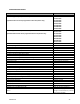
BASICCONNECTIONDIAGRAMKEY
ID Item1 Item2
W1 DownlinkPowerAmpOutput DownlinkRadiator
W5 DuplexerAntennaPort "OfftheAir"Antenna
W6 DuplexerDownlink Downlink8WaySplitter
W7 DuplexerUplink UplinkPowerAmplifierOutput
W9 Uplink8WaySplitter UplinkRadiator
W10 Uplink8WayCombiner UplinkPowerAmplifierInput
W14 Downlink8WayCombiner DownlinkPowerAmplifierInput
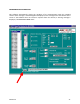
TheBasicConnectionDiagramshownabove,istheproperwaytheBDAshouldbeconnected
andonceupandrunning,requireminimaltononemanualconfiguration.Connectionsbetween
cabinetsaremadethroughN‐Bulkheadconnectorslocatedonthetopofeachcabinet.All
programmingandadjustingisdonethrough
thesoftwareandthismanualprimarilydealswith
thistopic.
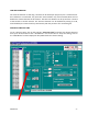
ThecomputerrunningthesoftwareisconnectedviaanRS232serialcabletoeachchannelcard
inthemannershownbelow.