
Integration Guide
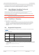

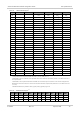
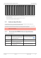


Table Of Contents
- 1.1. Accessories
- 1.2. Required Connectors
- 2.1. Power Supply
- 2.2. Module Power States
- 3.1. RF Connections
- 3.2. Sub-6G Antennas and Cabling
- 3.3. Ground Connection
- 3.4. Interference and Sensitivity
- 3.5. Radiated Sensitivity Measurement
- 3.6. Supported Frequencies
- 3.7. Antenna Specification
- 4.1. Important Notice
- 4.2. Safety and Hazards
- 4.3. Important Compliance Information for the United States and Canada

AirPrime EM9190 Hardware Integration Guide
RF Specifications
41113915
Rev 0.4
April 23, 2021
17
Parameter Requirements Comments
Total Radiated
Efficiency
> 50% on all bands
Measured at the RF connector.
Includes mismatch losses, losses in the
matching circuit, and antenna losses,
excluding cable loss.
Sierra Wireless recommends using
antenna efficiency as the primary
parameter for evaluating the antenna
system.
Peak gain is not a good indication of
antenna performance when integrated
with a host device (the antenna does not
provide omni-directional gain patterns).
Peak gain can be affected by antenna
size, location, design type, etc. — the
antenna gain patterns remain fixed
unless one or more of these parameters
change.
Radiation Patterns
Nominally Omni-directional radiation
pattern in azimuth plane.
Envelope
Correlation
Coefficient between
Ant
< 0.5 on Rx bands below 960 MHz
< 0.2 on Rx bands above 1.4 GHz
Mean Effective Gain
of Ant1 and Ant2
(MEG1, MEG2)
≥ -3 dBi
Ant1 and Ant2
Mean Effective Gain
Imbalance
| MEG1 / MEG2 |
< 2 dB for MIMO operation
< 6 dB for diversity operation
Maximum Antenna
Gain
Must not exceed antenna gains due to
RF exposure and ERP/ EIRP limits, as
listed in the module’s FCC grant.
See Important Compliance Information for
the United States and Canada.
Isolation
>10dB for all antennas at all bands
frequency range.
>20dB for Ant1 and Ant4 at B41
frequency range.
If antennas can be moved, test all
positions for both antennas.
Make sure all other wireless devices
(Bluetooth or WLAN antennas, etc.) are
turned OFF to avoid interference.
Power Handling
>1W
Measure power endurance over 4 hours
(estimated talk time) using a 1 W CW
signal — set the CW test signal
frequency to the middle of each
supporting Tx band.
Visually inspect device to ensure there is
no damage to the antenna structure and
matching components.
VSWR/TIS/TRP measurements taken
before and after this test must show
similar results.
1.
These worst-case VSWR figures for the transmitter bands may not guarantee RSE levels to be within regulatory limits.
The device alone meets all regulatory emissions limits when tested into a cabled (conducted) 50Ω system. With antenna
designs with up to 2.5:1 VSWR or worse, the radiated emissions could exceed limits. The antenna system may need to be
tuned in order to meet the RSE limits as the complex match between the module and antenna can cause unwanted levels
of emissions. Tuning may include antenna pattern changes, phase/delay adjustment, passive component matching.
Examples of the application test limits would be included in FCC Part 22, Part 24 and Part 27, test case 4.2.2 for WCDMA
(ETSI EN 301 908-1), where applicable.
2.
Ant1 - Primary, Ant2 - Secondary (Diversity/GNSS L1), Ant3 - MIMO1 Rx path and n41 TRx, Ant4 - MIMO2 Rx path,
n41 DRx path and GNSS L5.