
Integration Guide


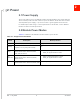
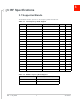
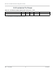
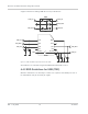
Table Of Contents

Rev. 1 July 2020 9 41114001
4
4: General Design Recommendations
This section describes general design recommendations for the AirPrime HL7800
module.
Note: This is a non-exhaustive list of suggested design guidelines. The developer is responsible for
deciding whether to implement these guidelines.
4.1 Host Application Board PCB
For details pertaining to PCB design requirements and industrial assembly of the
AirPrime HL7800 module on host applications, refer to Airprime HL78xx Customer
Process Guidelines, available at http://source.sierrawireless.com.
4.2 Power Supply
When designing the power supply, make sure that VBATT/VBATT_PA meet the
requirements listed in the AirPrime HL7800 Product Technical Specification, available at
http://source.sierrawireless.com.
The AirPrime HL7800 should not be supplied with voltage over 4.35V, even temporarily or
however briefly.
If the system's main board power supply unit is unstable or supplied with voltage over
4.35V, even in the case of transient voltage presence on the circuit, the module's power
amplifier may be severely damaged.
To avoid such issues, add a voltage limiter to the module's power supply lines so that
VBATT and VBATT_PA signal pads will never receive a voltage surge over 4.35V. The
voltage limiter can be as simple as a Zener diode.
4.3 Antenna
Sierra Wireless strongly recommends working with an antenna manufacturer either to
develop an antenna adapted to the application, or to adapt an existing solution to the
application.
4.4 ESD Guidlines
4.4.1 ESD Guidelines for USIM
Decoupling capacitors must be added according to the drawings below as close as
possible to the USIM connectors on UIM1_CLK, UIM1_RST, UIM1_VCC, UIM1_DATA and
UIM1_DET signals to avoid EMC issues and to comply with the requirements of ETSI and
3GPP standards covering the USIM electrical interface.