
Installation Manual
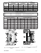

12 440 01 4900 00
Specifications subject to change without notice.
CONDENSATE TRAP
Condensate Trap -- Upflow Orientation
When the furnace is installed in the upflow position, it is not
necessary to relocate the condensate trap or associated tubing.
Refer to Fig. 9 for upflow condensate trap information. Refer to
Condensate Drain section for information how to install the
condensate drain.
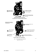
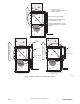
Condensate Trap -- Downflow Orientation.
When the furnace is installed in the downflow position, the
condensate trap will be initially located at the upper left corner of
the collector box, as received from the factory. See the top image
in Fig. 10. When the furnace is installed in the downflow
orientation, the condensate trap must be relocated for proper
condensate drainage. See the bottom image in Fig. 10.
To Relocate the Condensate Trap:
S Or i ent the furnace in the downflow position.
S Fig. 10 shows the condensate trap a nd tubing before and after
relocation. Refer to Fig. 10 to begi n the trap conversion.
S Refer to Condensate Dr a in section f or inf ormation how to ins tall the
condensa t e drain.
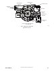
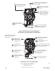
Condensate Trap -- Horizontal Orientation.
Whe n the furnace is ins talle d in the horizontal ri ght pos ition, the
condensa t e t r ap will be initially located at the bottom of the collector
box, as received from the factory. See the top image in Fig. 11.
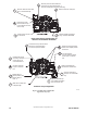
When the furnace is installed in the horizontal left position, the
condensa t e tr ap wil l be initially located at the top of the collector box,
as received from the factory. See the top image in Fig. 12. In both
case s the tr ap mus t be repositi oned on the col lector box for prope r
condensate drai nage. See the bott om im a ges in Fi g. 1 1 and 12.
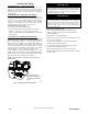
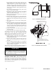
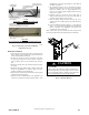
A field--supplied, accessory Horizontal Installation Kit (trap
grom met) i s re qui red for all dir ect--vent hori zontal ins tall ations (onl y).
The kit cont ains a rubber casing gromm et des igned to seal bet w ee n
the furnace ca sing a nd the c ondensate t rap. See Fi g. 8.
Remove knockout.
Install grommet before
relocating condensate
trap.
NOTE: Trap grommet is required only for direct-vent
applications.
A11582
Fig. 8 -- Horizontal Drain Trap Grommet
The field--supplied, accessory horizontal drain trap grommet is
ONLY REQUIRED FOR DIRECT VENT APPLICATIONS.
It it NOT required for applications using single--pipe or
ventilated combustion air venting.
NOTICE
The condensate trap extends below the side of the casing in
the horizontal position. A minimum of 2--in. (51 mm) of
clearance is required between the casing side and the furnace
platform for the trap to extend out of the casing in the
horizontal position. Allow at least 1/4 --in. per foot (20 mm
per meter) of slope down.
NOTICE
To Relocate the Condensate Trap:
S Rem ove the knockout in the ca sing for the condensate tr ap.
S Install the gromm et in t he casing when r equired for dire ct--ve nt
horizontal appl ications.
S Orient the furnace in the desired position.
S Allow for 2 in. (51 mm) of c le arance under neath the furnace for the
condensa t e trap a nd dra i n line.
S Fig. 11 shows the condensate trap and tubi ng bef or e and after
relocation in the hori zontal right posi tion.
S Fig. 12 shows the condensate trap a nd tubing before and after
relocation in the hori zontal left position.
S Refer to the appropriate figur e to begi n the trap c onversion.
S Refer to Condensate Dr a in section f or inf ormation how to ins tall the
condensa t e drain.