
Installation Manual

Specifications subject to change without notice.
440 01 4900 00 35
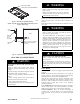
1ï1/2 inch for Gas
7/8 inch for 115 VAC Electric
A170125
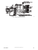
Fig. 31 -- Alternate Gas and Electric Entry
NOTE: Top plate may be field drilled for alternate gas and
1 15 VAC electric entry.
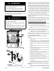
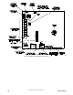
GAS
SUPPLY
MANUAL
SHUT OFF
VALVE
(REQUIRED)
SEDIMENT
TRAP
UNION
NOTE: Union may be inside the
vestibule where permitted by
local codes.
FRONT
A11035
Fig. 32 -- Typical Gas Pipe Arrangement
ELECTRICAL CONNECTIONS
ELECTRICAL SHOCK, FIRE OR EXPLOSION
HAZARD
Failure to follow safety warnings could result in
dangerous operation, serious injury, death or property
damage.
Improper servicing could result in dangerous operation,
serious injury , death or property damage.
-- Before servicing, disconnect all electrical power to
furnace.
-- When servicing controls, label all wires prior to
disconnection. Reconnect wires correctly.
-- Verify proper operation after servicing.
-- Always reinstall access doors after completing service
and maintenance.
!
WARNING
ELECTRICAL SHOCK HAZARD
Failure to follow this warning could result in personal
injury or death.
Blower door switch opens 115-- v power to control. No
component operation can occur. Do not bypass or close
switch with blower door removed.
!
WARNING
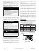
See Fig. 36 for field wiring diagram showing typical field 115--v
wiring. Check all factory and field electrical connections for
tightness.
Field--supplied wiring shall conform with the limitations of 63_F
(33_C) rise.
ELECTRICAL SHOCK AND FIRE HAZARD
Failure to follow this warning could result in personal
injury, death, or property damage.
The cabinet MUST have an uninterrupted or unbroken
ground according to NEC NFPA 70--2011 or local codes to
minimize personal injury if an electrical fault should occur.
In Canada, refer to Canadian Electrical Code CSA C22.1.
This may consist of electrical wire, conduit approved for
electrical ground or a listed, grounded power cord (where
permitted by local code) when installed in accordance with
existing electrical codes. Refer to the power cord
manufacturer’s ratings for proper wire gauge. Do not use
gas piping as an electrical ground.
!
WARNING
FURNACE MAY NOT OPERATE HAZARD
Failure to follow this caution may result in intermittent
furnace operation.
Furnace control must be grounded for proper operation or
else control will lock out. Control must remain grounded
through green/yellow wire routed to gas valve and manifold
bracket screw.
CAUTION
!
115-- V Wiring
Furnace must have a 115-v power supply properly connected and
grounded.
NOTE: Proper polarity must be maintained for 115-v wiring. If
polarity is incorrect, control LED status indicator light will flash
rapidly (Status Code 10) and furnace will NOT operate.
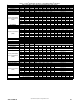
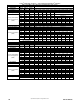
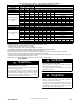
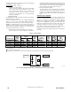
Verify that the voltage, frequency, and phase correspond to that
specified on unit rating plate. Also, check to be sure that service
provided by utility is sufficient to handle load imposed by this
equipment. Refer to rating plate or Table 11 for equipment
electrical specifications.
U.S.A. Installations: Make all electrical connections in accordance
with the current edition of the National Electrical Code (NEC)
NFPA 70 and any local codes or ordinances that might apply.
Canada Installations: Make all electrical connections in
accordance with the current edition of the Canadian Electrical
Code CSA C22.1 and any local codes or ordinances that might
apply.