
Installation Manual

36 440 01 4900 00
Specifications subject to change without notice.
FIRE HAZARD
Failure to follow this warning could result in personal
injury, death, or property damage.
Do not connect aluminum wire between disconnect
switch and furnace. Use only copper wire. See Fig. 34.
!
WARNING
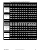
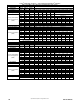
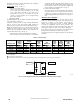
Use a separate, fused branch electrical circuit with a properly sized
fuse or circuit breaker for this furnace. See Table 11 for wire size
and fuse specifications. A readily accessible means of electrical
disconnect must be located within sight of the furnace.
J--Box Installation
FIRE OR ELECTRICAL SHOCK HAZARD
Failure to follow this warning could result in personal
injury, death, or property damage.
High voltage field connections must be located in J--Box
with furnace, or in field supplied external disconnect
mounted to furnace.
If field--supplied manual disconnect switch is to be mounted
on furnace casing side, select a location where a drill or
fastener cannot damage electrical or gas components.
!
WARNING
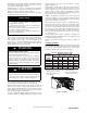
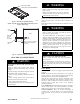
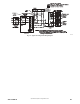
A12226
Fig. 33 -- Installing J--Box (When Used)
The J--Box must be used when field line voltage electrical
connections are made to the furnace wiring harness inside the
furnace casing. The J--Box cover is not required if an external
electrical box is attached to the outside of the furnace casing. The
field wiring and main wiring harness are grounded with the furnace
box is grounded to the green ground screw of the J--Box bracket
and the earth ground of the field electrical supply. The field ground
wire and furnace main ground wire are grounded when the J--Box
bracket is attached to the furnace and the field ground wire and
factory ground wire are secured to the bracket grounding screw. If
the J--Box cover is not used, the field and factory spliced
connections must be located inside the external electrical box. Do
not leave splice connections unprotected inside the furnace.
The J--Box cover, mounting bracket and screws are shipped in the
loose parts bag included with the furnace. See Fig. 33 for J--Box
mounting locations.
The J--Box mounting bracket and green ground screw is used as a
grounding point for all line voltage wiring options. The J--Box
cover may be omitted when electrical connections are made inside
an external electrical box mounted external to the casing.
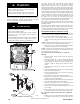
External Electrical Box on Furnace Casing
NOTE: Check to ensure that external electrical box does not
interfere with duct work, gas piping or the indoor coil drain. See
Fig. 31 for alternate electric entry through top panel.
1. Select and remove 7/8 --in. (22 mm) knock--out on the
desired side of the casing. Remove the knock --out from the
casing.
NOTE: If electrical entry through the furnace top panel is used, a
7/8--in. (22 mm) hole must be drilled through the top panel.
2. Drill two (2) 1/8-- in. (3 mm) pilot holes through the dimples
in the furnace casing near the 7/8 --in. knock-- out.
NOTE: If electrical entry through the furnace top panel is used,
mark the screw hole locations using the mounting holes in the
external electrical box as a template.
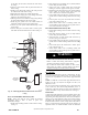
For a side--mounted external electrical box, complete the
following:
1. Align the J-- Box bracket with the knock-- out inside the
furnace casing.
2. Install the threaded end of a strain--relief bushing through
the J--Box bracket and the furnace casing. Strain--relief
bushing should be installed so that the bushing can be
tightened around the wiring harness inside the furnace
casing.
3. Align the external electrical box with the 7/8--in. (22 mm)
knock-- out.
4. Install and tighten the lock --nut on the strain-- relief bushing
inside the external electrical box.
5. Fasten the external electrical box to the furnace casing using
two (2) sheet metal screws.
6. Route field power wiring into external electrical box.
7. Pull furnace line voltage power wires through strain-- relief
bushing of the external electrical box.
8. Pull the ground wire of the field line voltage wiring through
the strain--relief bushing into the furnace casing.
9. Install the green ground screw to the J--Box bracket and
attach both ground wires to the green ground screw.
10. Connect any code required external disconnect(s) to field
power wiring.
11. Connect field power and neutral leads to furnace power
leads inside the external electrical box as shown in Fig. 32.
For a top panel--mounted external electrical box, complete the
following:
1. Drill two (2) 1/8-- in. (3 mm) pilot holes through the dimples
in the furnace casing near the 7/8 --in. knock-- out on the side