
Installation Manual

Specifications subject to change without notice.
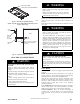
440 01 4900 00 37
of the casing. Do not remove the knock--out in the side of
the casing.
2. Align the J--Box bracket with the pilot holes inside the
furnace casing.
3. Install 2 screws through the outside of the casing to secure
the J--Box bracket to the furnace casing.
4. Route field power wiring into external electrical box.
5. Pull furnace line voltage power wires through strain-- relief
bushing of the external electrical box.
6. Pull the ground wire of the field line voltage wiring through
the strain--relief bushing into the furnace casing.
7. Install the green ground screw to the J--Box bracket and
attach both ground wires to the green ground screw.
8. Connect any code required external disconnect(s) to field
power wiring.
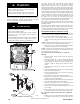
9. Connect field power and neutral leads to furnace power
leads inside the external electrical box as shown in Fig. 34.
COPPER
WIRE ONLY
ELECTRIC
DISCONNECT
SWITCH
ALUMINUM
WIRE
GROUND
NEUTRAL
LINE VOLTAGE
A11146
Fig. 34 -- Field--Supplied External Electrical Box on Furnace
Casing
Power Cord Installation in Furnace J--Box
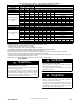
NOTE: Power cords must be able to handle the electrical
requirements listed in Table 11. Refer to power cord
manufacturer’s listings.
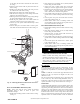
1. Install J--Box mounting bracket to inside of furnace casing.
See Fig. 33.
2. Route listed power cord through 7/8 --in. (22 mm) diameter
hole in casing and J-- Box bracket.
3. Secure power cord to J--Box bracket with a strain relief
bushing or a connector approved for the type of cord used.
4. Pull furnace power wires through 1/2 --in. (12 mm) diameter
hole in J--Box. If necessary, loosen power wires from
strain—relief wire--tie on furnace wiring harness.
5. Connect field ground wire and factory ground wire to green
ground screw on J-- Box mounting bracket as shown in Fig.
33.
6. Connect power cord power and neutral leads to furnace
power leads as shown in Fig. 36.
7. Attach furnace J--Box cover to mounting bracket with
screws supplied in loose parts bag. Do not pinch wires be-
tween cover and bracket. See Fig. 33.
BX Cable Installation in Furnace J--Box
1. Install J--Box mounting bracket to inside of furnace casing.
See Fig. 33.
2. Route BX connector through 7/8--in. (22 mm) diameter
hole in casing and J-- Box bracket.
3. Secure BX cable to J--Box bracket with connectors ap-
proved for the type of cable used.
4. Connect field ground wire and factory ground wire to green
ground screw on J-- Box mounting bracket as shown in Fig.
33.
5. Connect field power and neutral leads to furnace power
leads. as shown in Fig. 36.
6. Attach furnace J--Box cover to mounting bracket with
screws supplied in loose parts bag. Do not pinch wires be-
tween cover and bracket.
FIRE, EXPLOSION, ELECTRICAL SHOCK, AND
CARBON MONOXIDE POISONING HAZARD
Failure to follow this warning could result in dangerous
operation, personal injury, death, or property damage.
Do not drill into blower shelf of furnace to route control
wiring. Route any control or accessory wiring to the blower
compartment through external knockouts on the casing.
!
WARNING
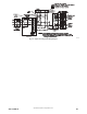
24--V Wiring
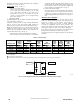
Make field 24 -- v connections at the 24--v terminal strip. See Fig.
37. Connect terminal Y/Y2 as shown in Fig. 36 for proper cooling
operation. Use only AWG No. 18, color-- coded, copper thermostat
wire.
NOTE: Use AWG No. 18 color-coded copper thermostat wire for
lengths up to 100 ft. (31 M). For wire lengths over 100 ft., use
AWG No. 16 wire.
The 24--v circuit contains an automotive--type, 3--amp. fuse located
on the control. Any direct shorts during installation, service, or
maintenance could cause this fuse to blow. If fuse replacement is
required, use ONLY a 3--amp. fuse of identical size. See Fig. 37.
Thermostats
A single stage heating thermostat can be used with the furnace. The
furnace control board CPU will control the furnace staging. A two
stage heating and cooling thermostat can also be used to control the
staging. For two stage thermostat control of the furnace staging,
turn SW1-2 ON at the furnace control board. A two stage cooling
thermostat must be used to control a 2-stage outdoor unit, remove.
Refer to typical thermostat wiring diagrams and the Sequence of
Operation section for additional details. Consult the thermostat