
Installation Manual


Specifications subject to change without notice.
440 01 4900 00 55
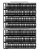
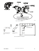
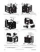
Long
Medium
Mitered
Concentric
Standard 2-in., 3-in., or
optional 4-in. termination.
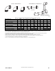
ELBOW CONFIGURATIONS
VENT TERMINAL CONFIGURATIONS
A13110
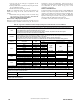
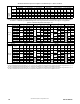
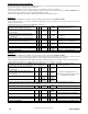
Table 17 – Deductions from Maximum Equivalent Vent Length -- Ft. (M)
Pipe Diameter (in): 1-1/2 2 2-1/2 3 4
Mitered 90º Elbow 8 (2.4) 8 (2.4) 8 (2.4) 8 (2.4) 8 (2.4)
Medium Radius 90º Elbow 5 (1.5) 5 (1.5) 5 (1.5) 5 (1.5) 5 (1.5)
Long Radius 90º Elbow 3 (0.9) 3 (0.9) 3 (0.9) 3 (0.9) 3 (0.9)
Mitered 45º Elbow 4 (1.2) 4 (1.2) 4 (1.2) 4 (1.2) 4 (1.2)
Medium Radius 45º Elbow 2.5 (0.8) 2.5 (0.8) 2.5 (0.8) 2.5 (0.8) 2.5 (0.8)
Long Radius 45º Elbow 1.5 (0.5) 1.5 (0.5) 1.5 (0.5) 1.5 (0.5) 1.5 (0.5)
Tee 16 (4.9) 16 (4.9) 16 (4.9) 16 (4.9) 16 (4.9)
Concentric Vent Termination NA 0 (0.0) NA 0 (0.0) NA
Standard Vent Termination0 0 (0.0) 0 (0.0) 0 (0.0) 0 (0.0) 0 (0.0)
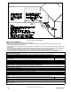
NOTES:
1. Use only the smallest diameter pipe possible for venting. Over ---sizing may cause flame disturbance or excessive vent terminal icing or freeze ---up.
2. NA --- Not allowed. Pressure switch will not close, or flame disturbance may result.
3. Vent sizing for Can a dian installations over 4500 ft. (1370 M) above sea level are subject to acceptance by the local author ities having jurisdiction.
4. Size both the combustion air and vent pipe independently , then use the larger size for both pipes.
5. Assume the two 45_ elbows equal one 90_ elbow. Wide radius elbows are desirable and may be required in some cases.
6. Elbow and pipe sections within the furnace casing and at the vent termination should not be included in vent length or elbow count.
7. The minimum pipe length is 5 ft. (2 M) linear feet (meters) for all applications.
8. Use 3 ---in. (76 mm) diameter vent termination kit for installations requiring 4---in. (102 mm) diameter pipe.