
Installation Manual


Specifications subject to change without notice.
440 01 4900 00 77
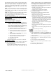
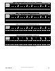
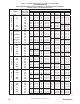
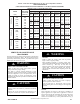
Table 19 -- Orifice Size and Manifold Pressure (In. W.C.) for Gas Input Rate (Continued)
SAGLARUTANFOYTIVARGCIFICEPSSAG.GVA
HEATVALUE0.580.600.620.64
AT ALTITUDE Orifice Mnfld Press Orifice Mnfld Press Orifice Mnfld Press Orifice Mnfld Press
(Btu/cu ft) No. High/Low No. High/Low No. High/Low No. High/Low
TWO-STAGE FURNACE
(TABULATED DATA BASED ON 20,000 BTUH HIGH-HEAT / 13,000 BTUH LOW-HEAT PER BURNER,
DERATED 2%/1000 FT (305M) ABOVE SEA LEVEL)
ALTITUDE
RANGE
ft (m)
650 42 3.4 / 1.4 42 3.5 / 1.5 42 3.6 / 1.5 42 3.7 / 1.6
7001 675 43 3.8 / 1.6 42 3.2 / 1.4 42 3.3 / 1.4 42 3.4 / 1.5
(2134) 700 43 3.5 / 1.5 43 3.7 / 1.5 43 3.8 / 1.6 42 3.2 / 1.4
725 44 3.8 / 1.6 43 3.4 / 1.4 43 3.5 / 1.5 43 3.6 / 1.5
750 44 3.5 / 1.5 44 3.7 / 1.5 44 3.8 / 1.6 43 3.4 / 1.4
8000 775 44 3.3 / 1.4 44 3.4 / 1.4 44 3.5 / 1.5 44 3.7 / 1.5
(2438) 800 45 3.8 / 1.6 44 3.2 / 1.4 44 3.3 / 1.4 44 3.4 / 1.4
825 46 3.7 / 1.6 46 3.8 / 1.6 45 3.8 / 1.6 44 3.2 / 1.4
625 42 3.4 / 1.4 42 3.5 / 1.5 42 3.6 / 1.5 42 3.7 / 1.6
8001 650 43 3.8 / 1.6 42 3.2 / 1.4 42 3.3 / 1.4 42 3.4 / 1.4
(2439) 675 43 3.5 / 1.5 43 3.6 / 1.5 43 3.7 / 1.6 42 3.2 / 1.3
700 44 3.7 / 1.6 43 3.4 / 1.4 43 3.5 / 1.5 43 3.6 / 1.5
725 44 3.5 / 1.5 44 3.6 / 1.5 44 3.7 / 1.6 44 3.8 / 1.6
9000 750 44 3.3 / 1.4 44 3.4 / 1.4 44 3.5 / 1.5 44 3.6 / 1.5
(2743) 775 45 3.7 / 1.6 44 3.2 / 1.3 44 3.3 / 1.4 44 3.4 / 1.4
9001 600 42 3.3 / 1.4 42 3.4 / 1.5 42 3.6 / 1.5 42 3.7 / 1.6
(2744) 625 43 3.7 / 1.6 42 3.2 / 1.3 42 3.3 / 1.4 42 3.4 / 1.4
650 43 3.5 / 1.5 43 3.6 / 1.5 43 3.7 / 1.6 43 3.8 / 1.6
675 44 3.7 / 1.6 44 3.8 / 1.6 43 3.4 / 1.4 43 3.5 / 1.5
10000 700 44 3.4 / 1.4 44 3.5 / 1.5 44 3.7 / 1.5 44 3.8 / 1.6
(3048) 725 44 3.2 / 1.3 44 3.3 / 1.4 44 3.4 / 1.4 44 3.5 / 1.5
* Orifice numbers shown in BOLD are factory-installed.
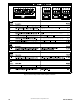
to
to
to
U.S.A. OnlyU.S.A. Only U.S.A. Only
A11252B
SERVICE AND MAINTENANCE
PROCEDURES
Untrained personnel can perform basic maintenance functions such
as cleaning and replacing air filters. All other operations must be
performed by trained service personnel. A qualified service person
should inspect the furnace once a year.
FIRE, INJURY OR DEATH HAZARD
Failure to follow this warning could result in personal
injury, death and/or property damage.
The ability to properly perform maintenance on this
equipment requires certain knowledge, mechanical skills,
tools, and equipment. If you do not possess these, do not
attempt to perform any service and maintenance on this
equipment other than those procedures recommended in the
Owner’s Manual.
!
WARNING
ENVIRONMENTAL HAZARD
Failure to follow this caution may result in environmental
pollution.
Remove and recycle all components or materials (i.e. oil,
refrigerant, control board, etc.) before unit final disposal.
CAUTION
!
ELECTRICAL SHOCK, FIRE OR EXPLOSION
HAZARD
Failure to follow this warning could result in personal
injury or death, or property damage.
Before installing, modifying, or servicing system, main
electrical disconnect switch must be in the OFF position and
install a lockout tag. There may be more than one
disconnect switch. Lock out and tag switch with a suitable
warning label. Verify proper operation after servicing.
Always reinstall access doors after completing service and
maintenance.
!
WARNING
ELECTRICAL OPERATION HAZARD
Failure to follow this caution may result in improper
furnace operation or failure of furnace.
Label all wires prior to disconnection when servicing
controls. Wiring errors can cause improper and dangerous
operation.
CAUTION
!
General
These instructions are written as if the furnace is installed in an
upflow application. An upflow furnace application is where the
blower is located below the combustion and controls section of the
furnace, and conditioned air is discharged upward. Since this
furnace can be installed in any of the 4 positions shown in Fig. 2,