INSTALLATION INSTRUCTIONS Two--Stage, Variable--Speed, Multipoise High Efficiency, 35 in. (889 mm) Tall, Condensing Gas Furnace F96CTN and G96CTN (Series A) NOTE: Read the entire instruction manual before starting the installation. SECTION TABLE SAFETY CONSIDERATIONS . . . . . . . . . . . . . . . . . . . . . . . . . 3 INTRODUCTION . . . . . . . . . . . . . . . . . . . . . . . . . . . . . . . . . . . 4 CODES AND STANDARDS . . . . . . . . . . . . . . . . . . . . . . . . . . .
Required Notice for Massachusetts Installations IMPORTANT The Commonwealth of Massachusetts requires compliance with regulation 248 CMR as follows: 5.08: Modifications to NFPA--54, Chapter 10 2) Revise 10.8.3 by adding the following additional requirements: a.
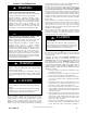
SAFETY CONSIDERATIONS WARNING ! FIRE, EXPLOSION, ELECTRICAL SHOCK, AND CARBON MONOXIDE POISONING HAZARD Failure to follow this warning could result in dangerous operation, personal injury, death, or property damage. Improper installation, adjustment, alteration, service, maintenance, or use can cause carbon monoxide poisoning, explosion, fire, electrical shock, or other conditions which may cause personal injury or property damage.
duct(s) sealed to the furnace casing and terminating outside the space containing the furnace. See “Air Ducts” section. 8. A gas--fired furnace for installation in a residential garage must be installed as specified in the warning box in the “Location” section. 9. The furnace may be used for construction heat provided that the furnace installation and operation complies with the first CAUTION in the LOCATION section of these instructions. 10.
In the state of Massachusetts: S This product must be installed by a licensed plumber or gas fitter. S When flexible connectors are used, the maximum length shall not exceed 36 in. (914 mm). S When lever type gas shutoffs are used they shall be T--handle type. S The use of copper tubing for gas piping is not approved by the state of Massachusetts. Electrical Connections S US: Current edition of National Electrical Code (NEC) NFPA 70 S CANADA: Current edition of Canadian Electrical Code CSA C22.
! WARNING CARBON MONOXIDE POISONING / COMPONENT DAMAGE HAZARD Failure to follow this warning could result in personal injury or death and unit component damage. Corrosive or contaminated air may cause failure of parts containing flue gas, which could leak into the living space. Air for combustion must not be contaminated by halogen compounds, which include fluoride, chloride, bromide, and iodide. These elements can corrode heat exchangers and shorten furnace life.
A180203 A B C D CABINET WIDTH OUTLET WIDTH BOTTOM INLET WIDTH AIR INTAKE SHIP WT. LB (KG) 0601714 17--- 1/2 (445) 15--- 7/8 (403) 16 (406) 8--- 3/4 (222) 151.0 (68.5) 0801714 17--- 1/2 (445) 15--- 7/8 (403) 16 (406) 8--- 3/4 (222) 152.5 (69.2) 0802120 21 (533) 19--- 3/8 (492) 19--- 1/2 (495) 10--- 1/2 (267) 171.5 (77.8) 1002122 21 (533) 19--- 3/8 (492) 19--- 1/2 (495) 10--- 1/2 (267) 179 (81.2) 1202422 24--- 1/2 (622) 22--- 7/8 (581) 23 (584) 12--- 1/4 (311) 188.5 (84.
THE BLOWER IS LOCATED BELOW THE BURNER SECTION, AND CONDITIONED AIR IS DISCHARGED UPWARD. THE BLOWER IS LOCATED TO THE RIGHT OF THE BURNER SECTION, AND CONDITIONED AIR IS DISCHARGED TO THE LEFT. THE BLOWER IS LOCATED TO THE LEFT OF THE BURNER SECTION, AND CONDITIONED AIR IS DISCHARGED TO THE RIGHT. THE BLOWER IS LOCATED ABOVE THE BURNER SECTION, AND CONDITIONED AIR IS DISCHARGED DOWNWARD A12181 Fig.
AIR FOR COMBUSTION AND VENTILATION ! WARNING Introduction CARBON MONOXIDE POISONING HAZARD Direct Vent (2-- pipe) Applications Failure to follow this warning could result in personal injury or death. When the furnace is installed as a direct vent (2-pipe) furnace, no special provisions for air for combustion are required. However, other gas appliances installed in the space with the furnace may require outside air for combustion.
Indoor Combustion AirE NFPA & AGA Standard and Known-- Air-- Infiltration Rate Methods Indoor air is permitted for combustion, ventilation, and dilution, if the Standard or Known--Air--Infiltration Method is used. WARNING ! CARBON MONOXIDE POISONING HAZARD Failure to follow this warning could result in personal injury or death. Many homes require air to be supplied from outdoors for furnace combustion, ventilation, and dilution of flue gases.
Table 3 – Minimum Free Area Required for Each Combustion Air Opening or Duct to Outdoors TWO HORIZONTAL DUCTS (1 SQ. IN./2,000 BTUH) (1,100 SQ. MM/KW) FURNACE INPUT (BTUH) TWO OPENINGS OR VERTICAL DUCTS (1 SQ. IN./4,000 BTUH) (550 SQ. MM/KW) SINGLE DUCT OR OPENING (1 SQ. IN./3,000 BTUH) (734 SQ. MM/KW) Free Area of Opening and Duct Sq. In (Sq. mm) Round Duct In. (mm) Dia Free Area of Opening and Duct Sq. In (Sq. mm) Round Duct In. (mm) Dia Free Area of Opening and Duct Sq. In (mm) Round Duct In.
CONDENSATE TRAP NOTICE Condensate Trap -- Upflow Orientation When the furnace is installed in the upflow position, it is not necessary to relocate the condensate trap or associated tubing. Refer to Fig. 9 for upflow condensate trap information. Refer to Condensate Drain section for information how to install the condensate drain. The field--supplied, accessory horizontal drain trap grommet is ONLY REQUIRED FOR DIRECT VENT APPLICATIONS.
Vent Pipe Clamp Condensate Trap Relief Port Vent Elbow Clamp Collector Box Plugs Vent Elbow Collector Box Plug Condensate Trap Relief Port Pressure Switch Port Condensate Trap Outlet UPFLOW TRAP CONFIGURATION 1 & 2 Stage Units A11307 Fig. 9 -- Upflow Trap Configuration (Appearance may vary) 440 01 4900 00 Specifications subject to change without notice.
Remove pressure switch tube from front pressure switch and discard. A new tube is shipped in the loose parts bag. Remove relief tube from relief port on condensate trap. Remove tube from relief port. Remove the screw that secures the trap to the collector box and remove trap. Loosen clamp on inlet to vent elbow. Remove middle and bottom plugs. DO NOT DISCARD.
Remove plug from collector box. DO NOT DISCARD. If alternate vent position is required, loosen clamp on inlet of vent elbow. Remove the screw that secures the trap to the collector box and remove trap. Unconverted Factory Configuration As Viewed in the Horizontal Right Orientation NOTE: Remove knockout in casing before reïinstalling the condensate trap. Slide relief tube in standïoffs to adjust length. Vent elbow shown in alternate orientation. Tighten clamp on inlet to vent elbow 15 lb.ïin.
5 If alternate vent position is required, loosen clamp on vent elbow inlet. Remove the screw that secures the condensate trap to the collector box and remove trap. Remove relief tube from relief port on condensate trap. Remove front pressure switch tube and discard. A new tube is shipped in the Loose Parts bag. Remove relief tube from port on collector box. Remove middle and right plug from collector box. DO NOT DISCARD.
CONDENSATE DRAIN CONNECTION ! CAUTION FROZEN AND BURST WATER PIPE HAZARD Failure to protect against the risk of freezing may result in property damage. Special precautions MUST be made if installing furnace in an area which may drop below freezing. This can cause improper operation or damage to equipment. If furnace environment has the potential of freezing, the drain trap and drain line must be protected.
6. From the outside of the casing, insert the angled end of the Z-pipe through drain hole in the left side of the casing and behind the inducer or gas valve. Allow the Z-pipe to temporarily rest on the blower shelf (upflow) or burner box (downflow). (NOTE: When the inducer housing has been removed to ease installation in upflow applications, this step is not needed.) 7. After inserting the Z pipe through the casing, slide a spring clamp over each end of the Z pipe. 8.
ATTACH ELBOW TO CONDENSATE TRAP CUT FORMED END OFF CONDENSATE DRAIN ELBOW FORMED END OF GROMMET CONNECT SHORT END OF ’Z’ PIPE TO MODIFIED DRAIN ELBOW FACTORY SUPPLIED 1/2ïIN. CPVC TO 3/4ïIN. PVC ADAPTER TOP VIEW DRAIN ELBOW “Z” DISCHARGE PIPE FOR LEFT SIDE DRAIN IS ROUTED BEHIND INDUCER FORMED END OF GROMMET. OPEN SPRING CLAMP, INSERT 1/2ïIN. TO 3/4ïIN. CPVC TO PVC ADAPTER OR CPVC PIPE misalignment of the drain pipe which may cause kinks in the elbow or grommet. 7.
Evaporator Coil + ++ + DIRECTION OF AIRFLOW + Condensing Furnace + + + + + - - - Furnace condensate does not flow consistently when drain is at positive pressure.
ÄÄÄÄÄÄÄÄÄÄ ÄÄÄÄÄÄÄÄÄÄ ÄÄÄÄÄÄÄÄÄÄ ÄÄÄÄÄÄÄÄÄÄ + ++ ÄÄÄÄÄÄÄÄÄÄ ÄÄÄÄÄÄÄÄÄÄ ÄÄÄÄÄÄÄÄÄÄ Evaporator Coil &RLO RU KXPLGLILHU GUDLQ ZKHQ XVHG DIRECTION OF AIRFLOW + Air gap here Open standpipe LQ KLJK PLQLPXP for coil or humidifier drain TEE (1/2” CPVC to 3/4” PVC adapter from loose parts bag.) 3/4” PVC 3/4 + Condensing Furnace + + + 3/4” PVC 3/4 + + Open standpipe LQ KLJK PLQLPXP Air gap required when another drain is connected to furnace drain.
UPFLOW PERFORATED DISCHARGE DUCT FLANGE DOWNFLOW HORIZONTAL 90° 90° YES YES YES 120° MIN YES 120° MIN YES 120° MIN NO NO YES NO A10493 Fig. 19 -- Duct Flanges Return Air Connections ! 3. Install another nut on other side of furnace base. (Install flat washer if desired.) 4. Adjust outside nut to provide desired height, and tighten inside nut to secure arrangement. 5. Reinstall bottom closure panel if removed.
3. Construct plenum to dimensions specified in Table 8 and Fig. 29. 4. Install special base coil assembly or coil box as shown in in Fig. 29. NOTE: It is recommended that the perforated supply--air duct flanges be completely removed from furnace when installing the furnace on a factory--supplied cased coil or coil box. To remove the supply--air duct flange, use wide duct pliers or hand seamers to bend flange back and forth until it breaks off. Be careful of sharp edges. See Fig. 19.
Connect supply--air duct to flanges on furnace supply--air outlet. Bend flange upward to 90_ with wide duct pliers. See Fig. 19. The supply--air duct must be connected to ONLY the furnace supply--outlet--air duct flanges or air conditioning coil casing (when used). DO NOT cut main furnace casing side to attach supply air duct, humidifier, or other accessories. All supply--side accessories MUST be connected to duct external to furnace main casing.
SCREWS (2) BOTTOM CLOSURE Representative drawing only, some models may vary in appearance. 1 2 SCREWS (4) Lay furnace on the back or side Remove the two (2) screws that secure the bottom closure panel to the furnace casing and remove the panel A170123 Fig. 25 -- Removing Bottom Closure Panel (2 Screws) BOTTOM PLATE Representative drawing only, some models may vary in appearance.
COMBUSTION-AIR PIPE (SEE VENTING SECTION) 2-IN. (51 mm) ROLLOUT PROTECTION REQUIRED Install 12” x 22” (204 x 559 mm) sheet metal in front of and above the burner compartment area. The sheet metal MUST extend above the furnace casing by 1-in. (25 mm with the door removed. A 1-in. (25 mm) clearance minimum between top of furnace and combustible material is required. The entire length of furnace must be supported when furnace is used in horizontal position to ensure proper drainage.
Design the filter and associated ductwork for the best match of pressure drop versus filter size. Best practice usually chooses filter systems with pressure drops under 0.2 in. W.C. (50 Pa), with the best blower electrical efficiency and system airflow performance occurring with filter pressure drops under 0.1 in. W.C. (25 Pa).
Table 6 – Filter Media Pressure Drop (Clean) Versus Face Velocity-- In. W.C. (Pa) Face Velocity Representative After-Market Filter Media* Factory-Accessory Washable (1-in. / 2.5 cm) Fiberglass* (1-in. / 2.5 cm) Pleated* FPM (m/s) (2-in. / 5 cm) (1-in. / 2.5 cm) 200 (1) 0.04 (10) 0.05 (13) 0.08 (20) 0.18 (47) 0.12 (2-in. / 5 cm) (31) 300 (1.5) 0.05 (14) 0.09 (22) 0.13 (34) 0.30 (75) 0.21 (52) 400 (2) 0.07 (17) 0.13 (32) 0.20 (50) - - 0.31 (78) 500 (2.5) 0.
FURNACE (OR COIL CASING WHEN USED) FURNACE APPROVED COIL ASSEMBLY OR COIL BOX COMBUSTIBLE FLOORING COMBUSTIBLE FLOORING A PLENUM OPENING D B DOWNFLOW SUBBASE FLOOR OPENING SHEET METAL PLENUM SHEET METAL PLENUM FLOOR OPENING C FLOOR OPENING A10491 Fig. 29 -- Installation on Combustible Flooring Table 8 – Opening Dimensions -- In. (mm) FURNACE CASING WIDTH IN.
AIR DUCTS Return Duct Sizing NOTICE Many states, provinces and localities are considering or have implemented standards and/or restrictions on duct sizing practices, ductwork leakage, and/or ductwork thermal, airflow and electrical efficiencies. CONSULT LOCAL CODE OFFICIALS for ductwork design and performance requirements in your area.
Table 9 – Cooling4 and Heating Air Delivery -- CFM (Bottom Return5 with Filter) Unit Size: 0601714 Clg Switches Clg Default: CF Switches Low--- Clg Default: Cooling Airflow (SW2) Low--- Cooling Airflow (SW3) CF Switches Cont. Fan Default: Continuous Fan Airflow (SW3) (SW1---5 and SW4---3 set to OFF, except as indicated. See notes 1 and 2.) Clg/CF Switch settings External Static Pressure (ESP) SW2--- 3 SW2--- 2 SW2--- 1 0.1 0.2 0.3 0.4 0.5 0.6 0.7 0.8 0.
Cooling4 and Heating Air Delivery -- CFM continued (Bottom Return5 with Filter) Unit size: 0802120 (SW1---5 and SW4---3 set to OFF, except as indicated. See notes 1 and 2.
Cooling4 and Heating Air Delivery -- CFM continued (Bottom Return5 with Filter) (SW1---5 and SW4---3 set to OFF, except as indicated. See notes 1 and 2.
Gas piping must be installed in accordance with national and local codes. Refer to current edition of NFGC in the U.S.A. Refer to current edition of NSCNGPIC in Canada. Installations must be made in accordance with all authorities having jurisdiction. If possible, the gas supply line should be a separate line running directly from meter to furnace. NOTE: Use a back--up wrench on the inlet of the gas valve when connecting the gas line to the gas valve. NOTICE In the state of Massachusetts: 1.
! 1ï1/2 inch for Gas 7/8 inch for 115 VAC Electric WARNING ELECTRICAL SHOCK HAZARD Failure to follow this warning could result in personal injury or death. Blower door switch opens 115--v power to control. No component operation can occur. Do not bypass or close switch with blower door removed. A170125 Fig. 31 -- Alternate Gas and Electric Entry NOTE: Top plate may be field drilled for alternate gas and 115 VAC electric entry. See Fig. 36 for field wiring diagram showing typical field 115--v wiring.
! WARNING FIRE HAZARD Failure to follow this warning could result in personal injury, death, or property damage. Do not connect aluminum wire between disconnect switch and furnace. Use only copper wire. See Fig. 34. Use a separate, fused branch electrical circuit with a properly sized fuse or circuit breaker for this furnace. See Table 11 for wire size and fuse specifications. A readily accessible means of electrical disconnect must be located within sight of the furnace.
2. 3. 4. 5. 6. 7. 8. 9. of the casing. Do not remove the knock--out in the side of the casing. Align the J--Box bracket with the pilot holes inside the furnace casing. Install 2 screws through the outside of the casing to secure the J--Box bracket to the furnace casing. Route field power wiring into external electrical box. Pull furnace line voltage power wires through strain--relief bushing of the external electrical box.
installation instructions for specific information about configuring the thermostat. See Fig. 37 and 38. an optional communicating User Interface instead of a standard thermostat. The communication plug is supplied with the User Interface. Refer to the instructions supplied with the User Interface for complete details. See Fig. 37. 4. Outside Air Thermistor (OAT) The OAT connection is used in conjunction with communicating User Interface.
W2 COM W/W1 Y/Y2 R G A11401 Fig. 36 -- Typical Two--Stage Field Wiring Diagram 440 01 4900 00 Specifications subject to change without notice.
A190154 Fig. 37 -- Example of Variable Speed Furnace Control 40 Specifications subject to change without notice.
Variable Speed Furnace with Single Stage Heat Pump (Dual Fuel) Variable Speed Furnace with Single Stage Air Conditioner NOTE 9 NOTE 9 Variable Speed Furnace with Two--Stage Air Conditioner NOTE 9 L09F026 Variable Speed Furnace with Two--Stage Heat Pump (Dual Fuel) NOTE 9 L09F027 Fig. 38 -- Thermostat Wiring Diagrams 1. 2. 3. 4. 5. 6. 7. L09F028 NOTES FOR THERMOSTAT WIRING DIAGRAMS Refer to outdoor equipment Installation Instructions for additional information and setup procedure.
VENTING NOTE: Planning for the venting system should be done in conjunction with planning for the ductwork, drainage, and furnace accessories, such as air cleaners and humidifiers. Begin assembling the venting system AFTER the furnace is set in place in the required orientation. Venting for this furnace shall follow all Local codes for Category IV venting systems. This furnace is CSA approved for venting with PVC/ABS DWV venting systems.
Venting Systems A furnace shall not be connected to a chimney flue serving a separate appliance designed to burn solid fuel. Other gas appliances with their own venting system may also use the abandoned chimney as a raceway providing it is permitted by local code, the current edition of the National Fuel Gas Code, and the vent or liner manufacturer’s installation instructions. Care must be taken to prevent the exhaust gases from one appliance from contaminating the combustion air of other gas appliances.
A combustion air pipe to the outdoors is not required for a single--pipe vent system. A 12-in. (304 mm) long pipe with a 2--in. (51 mm) tight radius 90 degree elbow is required to be attached to the combustion air pipe adapter on the furnace. See Fig. 56. This short inlet air pipe helps to ensure stable combustion, as well as allow for sound attenuation. To aid sound attenuation, point the inlet air pipe away from occupants.
Roof Termination (Preferred) Vent Maintain 12 in (305mm) . minimum clearance above highest anticipated snow level maximum of 24 in. (610mm) above. roof Abandoned masonry used as raceway (per code) 12 in. min. (305 mm)from overhang or roof 6 in. (152mm) minimum clearance between wall and end of vent pipe. 10 in. (254mm) maximum pipe length Maintain 12 in. (305mm) minimum clearance above highest anticipated snow level or grade whichever is greater 12 in. (305 mm) min.
to be attached to the furnace. See Fig. 56. This short inlet air pipe helps to ensure stable combustion, as well as allow for sound attenuation. To aid sound attenuation, point the inlet air pipe away from occupants. An extra elbow and/or five feet of pipe may be used to accomplish the sound attenuation function. Termination Requirements for the Provinces of Alberta and Saskatchewan The Provinces of Alberta and Saskatchewan require a minimum unobstructed distance of 4 ft. (1.
A A A TO CODE-- APPROVED DRAIN OR CONDENSATE PUMP Recommend “T” fitting with 4--inch minimum height standpipe (A) of same diameter or larger extending upward. Tee Tee Dry Well Cap (water tight and removable) Dry Well Tee Cap (water tight and removable) Dry Well Representative drawing only, some models may vary in appearance. Fig.
In any configuration, it will be necessary to add the equivalent length of the tee (15 feet/5 M) to the Total Equivalent Vent Length of the venting system. NOTICE ADDITIONAL INFORMATION FOR POLYPROPYLENE VENTING SYSTEMS Polypropylene venting systems include flexible vent pipe. These flexible vent pipes have a different equivalent vent length than straight sections of PVC/ABS DWV vent pipe.
Near Furnace Vent Connections Offsets in the vertical portion of the vent pipe should be made with 45 deg. elbows instead of 90 deg. elbows. Short horizontal runs of vent pipe are difficult to pitch correctly and may trap water in the vent pipe. Trapped water in the vent pipe may result in nuisance pressure switch tripping. Install the Vent and Combustion Air Pipes With the furnace installed in the required position, remove the desired knockouts from the casing.
17. Slope the vent and combustion air piping downward towards furnace. A minimum slope of at least 1/4-in. (6 mm) per linear ft.(1-in (25 mm) per 4 ft.(1.2 M)) with no sags between hangers is required. See Caution Box below. ! termination elbows as shown in Figs. 40, 39 and 56. For Ventilated Combustion Air Termination, See Fig. 57. 19. Use appropriate methods to seal openings where combustion air pipe and vent pipe pass through roof or sidewall.
11. Slide the end of the coupling with notches in it over the standoffs in the vent pipe adapter. 12. Tighten the clamp of the coupling over the vent pipe adapter. Torque the lower clamp around the vent pipe adapter to 15 lb--in. 13. Pilot drill a 1/8--in. hole in the combustion air pipe adapter. 14. Complete the vent and combustion air pipe as shown in “Install the Vent and Combustion Air Pipe.” Disassemble loose pipe fittings. Clean and cement using same procedures as used for system piping.
1. Cut two holes, one for each pipe, of appropriate size for pipe size being used. 2. Loosely install elbow in bracket (if used) and place assembly on combustion--air pipe. 3. Install bracket as shown in Fig. 40 and 56. NOTE: For applications using vent pipe option indicated by dashed lines in Fig. 40 and 39, rotate vent elbow 90_ from position. 4. Disassemble loose pipe fittings. Clean and cement using same procedures as used for system piping. DO NOT CEMENT POLYPROPYLENE FITTINGS.
Table 15 – Maximum Allowable Exposed Vent Lengths Insulation Table Maximum Allowable Exposed Vent Length in Unconditioned Space -- Ft. Unit Size 40,000* BTUH Uninsulated Winter Design Temp °F 60,000 BTUH 3/8-in. Insulation Uninsulated 1/2-in.
Maximum Allowable Exposed Vent Length in Unconditioned Space -- Meters (continued) Unit Size 120,000 BTUH Uninsulated Winter Design Temp °C 140,000 BTUH 3/8-in. Insulation Uninsulated 1/2-in. Insulation 3/8-in. Insulation 1/2-in. Insulation Pipe Dia. mm 64 76 102 64 76 102 64 76 102 64 76 102 64 76 102 64 76 102 -7 3.0 15.2 12.2 3.0 22.9 28.9 3.0 22.9 32.0 1.5 16.7 15.2 1.5 19.8 32.0 1.5 19.8 38.1 -18 3.0 6.1 4.6 3.0 16.8 13.7 3.0 19.8 15.2 1.5 7.
VENT TERMINAL CONFIGURATIONS ELBOW CONFIGURATIONS Concentric Long Medium Mitered Standard 2-in., 3-in., or optional 4-in. termination. A13110 Table 17 – Deductions from Maximum Equivalent Vent Length -- Ft. (M) Pipe Diameter (in): 1-1/2 2 2-1/2 3 4 Mitered 90º Elbow 8 (2.4) 8 (2.4) 8 (2.4) 8 (2.4) 8 (2.4) Medium Radius 90º Elbow 5 (1.5) 5 (1.5) 5 (1.5) 5 (1.5) 5 (1.5) Long Radius 90º Elbow 3 (0.9) 3 (0.9) 3 (0.9) 3 (0.9) 3 (0.9) Mitered 45º Elbow 4 (1.2) 4 (1.
Venting System Length Calculations The Total Equivalent Vent Length (TEVL) for EACH combustion air or vent pipe equals the length of the venting system, plus the equivalent length of elbows used in the venting system from Table 17. Standard vent terminations or factory accessory concentric vent terminations count for zero deduction. See vent system manufacturer’s data for equivalent lengths of flexible vent pipe or other termination systems.
TABS ON THE INDUCER OUTLET RESTRICTOR SNAP INTO THE SLOTS AT THE OUTLET OF THE INDUCER FOR USAGE: SEE MAXIMUM EQUIVALENT VENT LENGTH TABLE (10FT. (3.1 M) OF VENT OR LESS ONLY) A170006 Fig. 45 -- Inducer Vent Elbow Slope vent pipe back to the furnace at least ¼” per foot Avoid short horizontal offsets with 90 deg. Elbows. Short offsets can be difficult to slope and may trap condensate. Use 45 deg. Elbows where possible, to ensure condensate drainage. A14546 Fig.
A190032 Inside Corner Terminations Fig. 47 -- Inside Corner Termination Inside corner vent terminations are permitted provided that: S Only two exterior walls come together to form an angle of 90 degrees to 135 degrees. There are no other exterior walls attached to either wall to form an alcove. S The clearance distances apply when the vent is at least 3 feet (1 meter) from, but not more than 6 feet (2 meters) away from an inside corner.
7 Rotate vent elbow to required position. 3 6 2 5 4 5 1 Any other unused knockout may be used for combustion air connection. 4 Rotate vent elbow to required position. 5 1 3 2 & 5 6 7 UPFLOW LEFT CONFIGURATION DOWNFLOW LEFT CONFIGURATION A11309A A11311A Rotate vent elbow to required position. 4 5 1 2 5 3 7 6 2 5 1 Any other unused knockout may be used for combustion air connection. Any other unused knockout may be used for combustion air connection.
ALTERNATE COMBUSTION AIR CONNECTIONS HORIZONTAL LEFT ---VERTICAL VENT CONFIGURATION HORIZONTAL RIGHT ---VERTICAL VENT CONFIGURATION A11327A A11337 Alternate combustion air connection. 4 Rotate vent elbow to required position.
NOTES FOR VENTING OPTIONS 1. 2. 3. 4. 5. 6. 7. Attach vent pipe adapter with gasket to furnace casing. Align notches in rubber coupling over standoffs on adapter. Slide clamps over the coupling. Slide vent pipe through adapter and coupling into vent elbow. Insert vent pipe into vent elbow. Torque all clamps 15 lb.--in. Attach combustion air pipe adapter with gasket to furnace. Attach combustion air pipe to adapter with silicone. Pilot drill a1/8--in. hole in adapter and secure with a #7 x 1/2--in.
V V A12326 NOTE: The following is based upon National codes for gas appliances and is provided as a reference. Refer to local codes which may supersede these standards and/or recommendations.
V V A12325 NOTE: The following is based upon National codes for gas appliances and is provided as a reference. Refer to local codes which may supersede these standards and/or recommendations.
OPTIONAL TERMINATION BRACKET FOR 2-PIPE TERMINATIONS OPTIONAL BRACKET COUPLING 12-IN. (305 MM) 12 IN. (305 MM) SEPARATION BETWEEN BOTTOM OF COMBUSTION AIR AND BOTTOM OF VENT. 12-IN. (305 MM) ABOVE ANTICIPATED SNOW LEVEL COMBUSTION-AIR (ELBOW PARALLEL TO WALL) EXHAUST MAINTAIN 12 IN. (305 MM) CLEARANCE ABOVE HIGHEST ANTICIPATED SNOW LEVEL OR GRADE, WHICHEVER IS GREATER. OVERHANG CLEARANCE TO OVERHANG PER CODE 12 IN. (305 MM) MIN. GROUND LEVEL OR SNOW LEVEL A12221 Fig.
Ventilated Combustion Air intake pipe Pipe hangar 3” (76 mm) 12” (305 mm) Ventilated Combustion Air intake termination in crawl space CRAWL SPACE highest level of insulation ATTIC A10497 Fig. 57 -- Vent Terminations for Ventilated Combustion Air 440 01 4900 00 Specifications subject to change without notice.
START--UP, ADJUSTMENT, AND SAFETY CHECK NOTICE Important Installation and Start--up Procedures Failure to follow this procedure may result in a nuisance smoke or odor complaint. The manifold pressure, gas rate by meter clocking, temperature rise and operation must be checked after installation. Minor smoke and odor may be present temporarily after start--up from the manufacturing process. Some occupants are more sensitive to this minor smoke and odor.
Adjustments CAUTION ! ! UNIT OPERATION HAZARD Failure to follow this caution may result in intermittent unit operation or performance satisfaction. Condensate trap must be PRIMED or proper draining may not occur. The condensate trap has two internal chambers which can ONLY be primed by pouring water into the inducer drain side of condensate trap. 1. Remove upper and middle collector box drain plugs opposite of the condensate trap. See Fig. 58. 2. Connect field-supplied 5/8--in.
EXAMPLE 1 NOTICE The NATURAL GAS manifold pressure adjustments in Table 21 compensate for BOTH altitude AND gas heating value. DO NOT apply an additional derate factor to the pressures shown in Table 21. The values in this table are NOT referenced to sea level; they are AS--MEASURED AT ALTITUDE. The heating content of natural gas at altitude may already provide for a reduction in capacity of the furnace.
c. Connect a water column manometer or similar device to manifold pressure tap. d. Turn gas valve ON/OFF switch to ON. e. Move setup SW1--2 on furnace control to ON position to lock furnace in low--heat operation. See Fig. 64 and Fig. 37. f. Manually close blower door switch. g. Jumper R and W/W1 thermostat connections on control to start furnace. See Fig. 37. h.
2. Restore furnace to normal operating condition. a. Turn gas valve ON/OFF switch to OFF. b. Remove water column manometer or similar device from manifold pressure tap. ! WARNING FIRE HAZARD Failure to follow this warning could result in personal injury, death, and/or property damage. Manifold pressure tap set screw must be tightened or ⅛--in. NPT pipe plug must be installed to prevent gas leaks. c. Tighten set screw on manifold pressure tap with 3/32--in hex wrench, or if 1/8--in.
The Continuous Fan airflow selection via Setup switches SW3 is also the switch setting for low-speed cooling when the furnace is used with a 2-speed cooling or heat pump unit. Adjust the Continuous Fan CFM Setup switches SW3 to match the airflow required for low-speed cooling. Select the required airflow from Table 9 and Fig. 64. NOTE: The airflow selected via SW3 (Low-Speed Cooling Airflow) cannot exceed the airflow selected via SW2 (High-Speed Cooling Airflow).
A190158 Fig. 63 -- Service Label Information 72 Specifications subject to change without notice.
A190161 Fig. 64 -- Furnace Setup Switches and Description 440 01 4900 00 Specifications subject to change without notice.
A190155 Fig. 64 -- Furnace Setup Switches and Description (Continued) 74 Specifications subject to change without notice.
Table 18 – Altitude Derate Multiplier for U.S.A. ALTITUDE Table 19 – Blower Off Delay Setup Switch 0–2000 0---610 SW1--- 7 SW1--- 8 2001–3000 610---914 4--- 6 0.95 90 OFF OFF 3001–4000 914---1219 6--- 8 0.93 120 ON OFF 4001–5000 1219---1524 8--- 10 0.91 150 OFF ON 5001–6000 1524---1829 10--- 12 0.89 180 ON ON 6001–7000 1829---2134 12--- 14 0.87 7001–8000 2134---2438 14--- 16 0.85 8001–9000 2438---2743 16--- 18 0.83 9001–10,000 2743---3048 18--- 20 0.
Table 21 – Orifice Size and Manifold Pressure (In. W.C.) for Gas Input Rate TWO-STAGE FURNACE (TABULATED DATA BASED ON 20,000 BTUH HIGH-HEAT / 13,000 BTUH LOW-HEAT PER BURNER, DERATED 2%/1000 FT (305M) ABOVE SEA LEVEL) ALTITUDE AVG. GAS RANGE HEAT VALUE AT ALTITUDE U.S.A. and Canada ft (m) U.S.A. and Canada U.S.A. Only U.S.A. Only 0.62 0.64 No. High/Low No. High/Low No. High/Low No. High/Low 900 43 3.8 / 1.6 42 3.2 / 1.4 42 3.3 / 1.4 42 3.4 / 1.4 0 925 43 3.6 / 1.5 43 3.7 / 1.
Table 19 -- Orifice Size and Manifold Pressure (In. W.C.) for Gas Input Rate (Continued) TWO-STAGE FURNACE (TABULATED DATA BASED ON 20,000 BTUH HIGH-HEAT / 13,000 BTUH LOW-HEAT PER BURNER, DERATED 2%/1000 FT (305M) ABOVE SEA LEVEL) ALTITUDE AVG. GAS RANGE HEAT VALUE AT ALTITUDE U.S.A. Only ft (m) 0.62 0.64 No. High/Low No. High/Low No. High/Low No. High/Low 650 42 3.4 / 1.4 42 3.5 / 1.5 42 3.6 / 1.5 42 3.7 / 1.6 7001 675 43 3.8 / 1.6 42 3.2 / 1.4 42 3.3 / 1.4 42 3.4 / 1.
you must revise your orientation to component location accordingly. Electrical Controls and Wiring Each pressure switch is labeled with the reference location (noted as “COLLECTOR BOX--LPS” or “HOUSING--HPS” on the switch). The nominal break point of each switch is shown on the label below the reference location in inches of water column, “W.C.” The maximum and minimum break point of the switch is +/-- 0.05 inches of water column from the nominal break point of the switch.
Care and Maintenance ! WARNING FIRE OR EXPLOSION HAZARD Failure to follow this warning could result in personal injury, death and/or property damage. Never store flammable or combustible materials on, near, or in contact with the furnace, such as: 1. Spray or aerosol cans, rags, brooms, dust mops, vacuum cleaners, or other cleaning tools. 2.
3. All factory wires can be left connected, but field thermostat and accessory wiring may need to be disconnected depending on their length and routing. 4. If the vent and combustion air pipe passes through the blower compartment, it will be necessary to remove the pipes from the blower compartment. Disconnect the vent and combustion air pipe by: a. Loosen the clamps on the vent couplings and combustion air pipe external to the furnace. b. Separate the pipes from the couplings and move them aside. c.
! WARNING ELECTRICAL SHOCK AND FIRE HAZARD Failure to follow this warning could result in personal injury, death, and/or property damage. Turn off the gas and electrical supplies to the furnace and install lockout tag before performing any maintenance or service. Follow the operating instructions on the label attached to the furnace. BURNER SUPT. ASSY IGNITER BRACKET, IGNITER BURNER ASSY FLAME ROLLOUT SWITCH 3.
14. Check for gas leaks with a commercially available soap solution made specifically for the detection of leaks. 15. Turn gas on at electric switch on gas valve and at external shut-off or meter 16. Turn power on at external disconnect, fuse or circuit breaker. 17. Run the furnace through two complete heating cycles to check for proper operation 18. Install control door when complete. Servicing Hot Surface Igniter The igniter does NOT require annual inspection. Check igniter resistance before removal.
where heat tape has been applied, check to ensure it will operate when low temperatures are present. NOTE: The Heat Pad, when used, should be wrapped around the condensate drain trap. There is no need to use heat tape within the furnace casing. Most heat tapes are temperature activated, and it is not practical to verify the actual heating of the tape. Check the following: 1. Check for signs of physical damage to heat tape such as nicks, cuts, abrasions, gnawing by animals, etc. 2.
WINTERIZATION ! GROMMET MOTOR SHAFT FLAT MOTOR ARM CAUTION SCREW SET SCREW UNIT AND PROPERTY DAMAGE HAZARD MOTOR WHEEL HUB Failure to follow this caution may result in unit component or property damage. If the furnace is installed in an unconditioned space where the ambient temperatures may be 32_ F (0_ C) or lower, freeze protection measures must be taken to prevent minor property or product damage.
on--time (from 0 to 16 minutes) which is permitted before switching to high--heat. If the power is interrupted, the stored history is erased and the control CPU will select low--heat for up to 16 minutes and then switch to high--heat, as long as the thermostat continues to call for heat. Subsequent selection is based on stored history of the thermostat cycle times. The wall thermostat “calls for heat”, closing the R--to--W circuit.
valve solenoid GV--M will remain energized as long as the low--heat pressure switch LPS remains closed. The blower motor BLWM will transition to low--heat airflow five sec after the R--to--W2 circuit opens. 3. Cooling mode The thermostat “calls for cooling”. a. Single--Speed Cooling-See Fig. 37 and 38 for thermostat connections The thermostat closes the R--to--G--and--Y circuits.
will transition to or bring on the blower motor BLWM at cooling airflow, low--heat airflow, or the mid--range airflow, whichever is lowest. The blower motor BLWM will remain on until the main burners ignite then shut OFF and remain OFF for 25 sec before coming back on at heating airflow. When the W/W1 input signal disappears, the furnace control begins a normal inducer post--purge period while changing the blower airflow.
A190162 Fig. 70 -- Troubleshooting Guide 88 Specifications subject to change without notice.
A190163 Troubleshooting Guide (Continued) 440 01 4900 00 Specifications subject to change without notice.
A190164 Troubleshooting Guide (Continued) 90 Specifications subject to change without notice.
A190153 Fig. 71 -- Wiring Diagram 440 01 4900 00 Specifications subject to change without notice.
PARTS REPLACEMENT INFORMATION GUIDE Casing Group Gas Control Group Blower door Bottom plate Control door Door knob assembly Top filler plate Burner Flame sensor Gas valve Hot surface igniter Manifold Orifice Electrical Group 3--Amp fuse Circuit board Control box Door switch Junction box Limit switch(es) Transformer Heat Exchanger Group Blower Group Inducer Group Blower housing Blower motor Blower wheel Cut--off plate Power choke (where used) Collector box Condensate trap Condensate trap elbow Gaske