
Natural Gas to Propane Conversion Instructions


AG--KC019SNP--02 3
Specifications subject to change wi thout notice.
MANIFOLD/ORIFICE/BURNER
REMOVAL
! CAUTION
UNIT OPERATION HAZARD
Failure to follow this caution may result in unit damage or
improper operation.
Label all wires prior to disconnection when servicing controls.
!
PRUDENCE
D’EQUIPEMENT D’OPERATION
Toute erreur de câblage peut être une source de danger et de
panne.
Lors des opérations d’entretien des commandes, étiqueter
tous les fils avant de les déconnecter.
NOTE:Use a back--up wrench on the gas valve to prevent the
valve from rotating on the manifold or damaging the mounting to
the burner box.
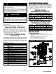
1. Disconnect the gas pipe from gas valve and remove pipe
from the furnace casing. (See Figure 1)
2. Disconnect the connector harness from gas valve
Disconnect wires from Hot Surface Igniter (HSI) and
Flame Sensor.
3. Support the manifold and remove the four (4) screws that
secure the manifold assembly to the burner box and set
aside.
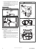
4. Note the location of the green/yellow wire ground wire for
re--assembly later. (See Figure 2)
5. Remove wires from both rollout switches. (See Figure 3)
6. Slide one --piece burner assembly out of slots on sides of
burner box. (See Figure 3)
7. Remove the flame sensor from the burner assembly.
8. Remove the orifices from the manifold and discard.
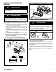
Figure 2 Manifold Assembly
Orifice
Connect Green/Yellow
ground wire here
Manifold
Gas Valve
Gas valve must be installed on
manifold with minimum engagement of
6 threads. Cross threading is not
acceptable.
Indicated surfaces
to be 90
˚+ or -2˚
C
L
Gas valve is parallel to manifold
within + or - 3˚
A11407
Figure 3 Burner
A
ssembly
FLAME SENSOR
(BELOW BURNER)
FLAME ROLLOUT
SWITCH
BRACKET, IGNITER
IGNITER
BURNER SUPT. ASSY
BURNER ASSY
A11403
ORIFICE SELECTION/DERATE
! CAUTION
UNIT DAMAGE HAZARD
Failure to follow this caution may result in unit damage.
DO NOT re--drill burner orifices. Improper drilling may result in
burrs, out --of--round holes, etc. Obtain new orifices if orifice
size must be changed. (See Figure 4)
Figure 4 Burner Orifice
BURNER
ORIFICE
BURNER
ORIFICE
A96249
Refer to conversion kit rating plate 344675--201 to determine
main burner orifice size. (See Figure 5)
Furnace gas input rate on furnace rating plate is for installations
at altitudes up to 2000 ft. (610 M).
In the U.S.A.; the input rating for altitudes above 2000 ft. (610
M) must be reduced by 2 percent for each 1000 ft. (305 M)
above sea level.
In Canada, the input rating must be derated by 5 percent for
altitudes of 2000 ft. to 4500 ft. (610 M to 1372 M) above sea
level.
The Conversion Kit Rating Plate accounts for high altitude
derate.