
Natural Gas to Propane Conversion Instructions


6 AG--KC019SNP--02
Specifications subject to change wi thout notice.
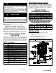
Figure 7 Mixer Screw Location
1.9”
(48.76 mm)
1.8”
(46.96 mm)
Drill out with
7/64” drill bit
A11460
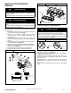
REINSTALL BURNER ASSEMBLY
To reinstall burner assembly:
1. Attach flame sensor to burner assembly.
2. Insert one-piece burner in slot on sides of burner box and
slide burner back in place.
3. Reattach HSI wires to HSI.
4. Verify igniter to burner alignment. (See Figure 8 &
Figure 9)
Figure 8 Igniter Position -- Back View
A11405
2-1/2-in.
(64.4)
1-1/4-in.
(31.8)
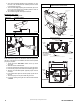
Figure 9 Igniter Position -- Side View
A12392
2 − in.
(2.5 mm
3/8 − in.
3/16− in.
, +0.8 -1.5)
(50 mm)
(9.6 mm)
(4.6 mm)
3/32− in., +1/32 -3/64-in.
CONVERT GAS VALVE
! CAUTION
UNIT OPERATION HAZARD
Failure to follow this caution may result in unit damage or
improper operation.
Do NOT use this kit if the gas valve has a green label
(26,000 BTUH model) on it shown in Figure 10. The 26,000
BTUH model uses a different conversion kit available from
your distributor.
The 26,000 BTUH model uses a different conversion kit. Refer
to Product Specification for the correct conversion kit,
available from your distributor.
NOTE: Do not use this kit if the gas valve in Figure 10 has a
green label on top of the valve. The green label on the gas valve
is a special low capacity gas valve. Refer to Specification Sheet
for the correct conversion kit.
! CAUTION
UNIT DAMAGE HAZARD
Failure to follow this caution may result in unit damage
The gas valve must be converted and pre--adjusted before
operating on propane gas. If not converted and pre--adjusted,
sooting and corrosion will occur leading to early heat
exchanger failure.
! W
A
RNING
FIRE, EXPLOSION, ELECTRICAL SHOC
K
HAZARD
Failure to follow this warning could result in personal injury,
death or property damage.
Gas s upply MUST be shut off before disconnecting electrical
power and proceeding with conversion.
! W
A
RNING
ELECTRICAL SHOCK, FIRE OR EXPLOSION HAZARD
Failure to follow this warning could result in personal injury,
death or property damage.
Before installing, modifying, or servicing system, main
electrical disconnect switch must be in the OFF position and
install a lockout tag. There may be more than one disconnect
switch. Lock out and tag s witch with a suitable warning label.
Verify proper operation after servicing.
Single Stage Gas Valve
1. Refer to Figure 10. Verify the gas valve has a white label
with black lettering on top of the operator.
2. Be sure gas and electrical supplies to furnace are off.
3. Remove caps that conceal adjustment screws for the
gas --valve regulators. (See Figure 10)
4. Remove the regulator adjustment screw.
5. Remove the regulator springs (silver).
6. Install the propane gas regulator springs (white).
7. Install the regulator adjustment screws.
8. Turn the adjusting screw clockwise (in) 8.5 full turns. This
will increase the manifold pressure closer to the propane
set point. (See Figure 10)