
Installation Manual

2 484 01 3601 02
Specifications subject to change without notice.
INSTALLATION
These units can be installed in multiple configurations. Before
installation, there are several performance requirements that
must be considered because poor installation can negatively
alter performance. This section will briefly discuss those factors.
Airflow
Airflow amount and distribution are vital to adequate system
performance. Problems that can be experienced with incorrect
airflow include:
S low system performance
S restricted TXV
S frosted coil
S poor humidity control
S water blow−off
When attaching the coil and building the plenum, pay special
attention to the effect these details will have on airflow. After
system start−up, check the cfm to insure that it is correct.
(Generally, the cfm should be 350 to 400 cfm/ton during normal
cooling operation.)
Cabinet Sweating
If this unit is installed in a garage, attic, or other unconditioned
space, special attention needs to be given to the potential of
cabinet sweating. A 6−in (152 mm) wide piece of insulation
should be wrapped around the coil casing and supply duct
connection point.
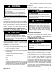
Inspect Equipment
File claim with shipper if equipment is damaged.
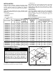
Table 1
END4X, ENW4X COIL INFORMATION
MODEL NUMBER TONS
FLUSH FIT TO
FURNACE WIDTH
inches (mm)
COIL CONNECTION
TUBE SIZE
inches (mm)
SHELF WIDTH
(See Figure 1,
Dim. A)
inches (mm)
FITS NEXT SMALLER FURNACE
Equal
Overhang
Overhang with
Transition
Offset Left
Liquid Suction
END4X18L14A 1-1/2 14-3/16 (360) 3/8 5/8 12-7/8 (327) N/A N/A N/A
END4X19L17A 1-1/2 17-1/2 (445) 3/8 5/8 16-3/16 (411) No Yes Yes
END4X24L14A 2 14-3/16 (360) 3/8 5/8 12-7/8 (327) N/A N/A N/A
END4X24L17A 2 17-1/2 (445) 3/8 5/8 16-3/16 (411) No Yes Yes
END4X30L14A 2-1/2 14-3/16 (360) 3/8 3/4 12-7/8 (327) N/A N/A N/A
END4X30L17A 2-1/2 17-1/2 (445) 3/8 3/4 16-3/16 (411) No Yes Yes
END4X31L17A 2-1/2 17-1/2 (445) 3/8 3/4 16-3/16 (411) No Yes Yes
END4X36L17A 3 17-1/2 (445) 3/8 3/4 16-3/16 (411) No Yes Yes
END4X36L21A 3 21 (533) 3/8 3/4 19-5/8 (498) No Yes Yes
END4X37L17A 3 17-1/2 (445) 3/8 3/4 16-3/16 (411) Yes No No
END4X42L17A 3-1/2 17-1/2 (445) 3/8 7/8 16-3/16 (411) No Yes Yes
END4X42L21A 3-1/2 21 (533) 3/8 7/8 19-5/8 (498) No Yes Yes
END4X43L24A 3-1/2 24-1/2 (622) 3/8 7/8 23-1/8 (587) No Yes Yes
END4X48L21A 4 21 (533) 3/8 7/8 19-5/8 (498) No Yes Yes
END4X48L24A 4 24-1/2 (622) 3/8 7/8 23-1/8 (587) No Yes Yes
END4X60L24A 5 24-1/2 (622) 3/8 7/8 23-1/8 (587) No Yes Yes
END4X61L24A 5 24-1/2 (622) 3/8 7/8 23-1/8 (587) No Yes No
ENW4X36L17A 3 17-1/2 (445) 3/8 3/4 16-3/16 (411) Yes No No
ENW4X42L21A 3-1/2 21 (533) 3/8 7/8 19-5/8 (498) Yes No No
ENW4X48L21A 4 21 (533) 3/8 7/8 19-5/8 (498) Yes No No
ENW4X60L24A 5 24-1/2 (622) 3/8 7/8 23-1/8 (587) Yes No No
Select Installation Procedure
PROPERTY DAMAGE HAZARD
Failure to follow this caution may result in property damage.
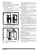
Installing coils rotated 90_ from the front of the furnace, in
upflow or downflow applications, may cause water blow−off
or coil freeze−up due to the concentration of air on one slab
of the coil or lack of air to a slab in the coil. It is
recommended that on this type of application, a
field−supplied adapter be placed between the coil and
furnace to allow air to distribute properly between all slabs
of the coil.
CAUTION
!
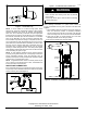
See Table 1 for dimensions and overhang options. Refer to
instructions for placement of coil casing on furnace.
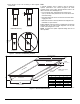
Field-supplied
Plenum
Field
Coil
Support Shelf
Furnace
See
Table 1
A
1
3
⁄
16
″
1
1
⁄
16
″
2
1
⁄
4
″
1
⁄
2
″
6″
19
3
⁄
16
″
(487)
(13)
(27)
(30)
(152)
(57)
A08336
Figure 1 − Correct Orientation of Coil Support on Furnace