
Installation Manual

484 01 3601 02 5
Specifications subject to change without notice.
Refrigerant Line Connections
PERSONAL INJURY HAZARD
Failure to follow this warning could result in personal
injury.
Wear eye protection.
Coil is factory charged with 15 psi nitrogen. The coil is
under pressure and TXV screen is in place behind liquid
line plug. DO NOT remove liquid line plug first, always
remove the suction line plug first to depressurize the coil.
!
WARNING
NOTE: Factory nitrogen charge may escape past rubber plugs
during storage. This does not indicate a leaking coil nor warrant
return of the coil.
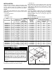
Size and install refrigerant lines according to information provided
with outdoor unit. Coil connection tube sizes are shown in Table 1.
Route refrigerant lines to the coil in a manner that will not obstruct
service access to the unit or removal of the filter.
Do not use damaged, dirty, or contaminated tubing because it
may plug refrigerant flow−control device. ALWAYS evacuate the
coil and field−supplied tubing before opening outdoor unit
service valves.
Connect Refrigerant Liquid and Suction Lines
For matched and mismatched systems, use line sizes
recommended in outdoor unit Installation Instructions.
UNIT OR PROPERTY DAMAGE HAZARD
Failure to follow this caution may result in property damage.
Take precautions to ensure Aluminum tubes do not come in
direct contact or allow for condensate run off with a dissimilar
metal. Dissimilar metals can cause galvanic corrosion and
possible premature failure.
CAUTION
!
The coil can be connected to outdoor units using field−supplied
tubing of refrigerant grade. Always evacuate tubing and reclaim
refrigerant when making connections or flaring tubing. Leak
check connections before insulating entire suction line.
See Table 1 for coil connection tube size.
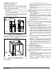
1 Remove cabinet access door.
2 Remove rubber plugs, suction plug then liquid plug, from coil
stubs using a pulling and twisting motion. Hold coil stubs
steady to avoid bending or distorting.
3 Remove tubing plate with rubber grommets and slide plate
with grommets onto the refrigerant lines (field line−set), away
from braze joints.
4 Fit refrigerant lines into coil stubs. Wrap a heat sinking
material such as a wet cloth behind braze joints.
5 Wrap TXV and nearby tubing with a heat−sinking material
such as a wet cloth.
6 Use 1/2 psig Nitrogen purge in the suction and out the liquid
line.
7 Braze using a Sil−Fos or Phos−copper alloy. Do not use soft
solder.
8 After brazing, allow joints to cool. Carefully remove TXV bulb
insulation and verify that the TXV bulb is securely fastened
with hose clamp. Tighten screw a half−turn past hand tight
with TXV bulb placed in the indentation with full contact with
the vapor line tube. Re−wrap TXV bulb with insulation.
9 Leak check connections before insulating entire suction line.
10 Slide tubing plate with rubber grommets over joints. Position
tubing at center of each grommet to ensure an air seal
around the tube. Reinstall cabinet door.
Suction Line
Suction line is designed for field sweat connection. Line is
plugged to keep out moisture and dirt. Remove these plugs only
when ready to make connection.
UNIT DAMAGE HAZARD
Failure to follow this caution may result in product damage.
To avoid valve damage to the refrigerant control device
while brazing, valves must be wrapped with a heat−sinking
material such as a wet cloth.
CAUTION
!
UNIT DAMAGE HAZARD
Failure to follow this caution may result in product damage.
DO NOT BURY MORE THAN 36 IN. OF REFRIGERANT
TUBING IN GROUND. If any section of tubing is buried,
there must be a 6 in. vertical rise to the valve connections
on the outdoor unit. If more than the recommended length is
buried, refrigerant may migrate to cooler buried section
during extended periods of unit shutdown, causing
refrigerant slugging and possible compressor damage at
start−up.
CAUTION
!
Refrigerant Metering Device
END4X, ENW4X coils have a factory−installed hard shut−off
TXV designed only for use with R−410A refrigerant. Use only
with outdoor units designed for R−410A.
NOTE: ALL TXV’S HAVE PRESET SUPERHEAT SETTINGS
AND ARE NOT FIELD−ADJUSTABLE.
Condensate Drain Line Connection
PROPERTY DAMAGE HAZARD
Failure to follow this caution may result in property damage.
When installing over a finished ceiling and/or living area,
install a field−fabricated secondary condensate pan under
the entire unit.
CAUTION
!
The coil is designed to dispose of accumulated water through
built−in condensate drain fittings. It is recommended that PVC
fittings be used on the condensate pan. Do not over−tighten.
Finger tighten plus 1−1/2 turns. Be sure to install plastic plug in
unused condensate drain fitting. Two 3/4 inch female threaded
pipe connections are provided in each coil condensate pan.
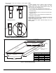
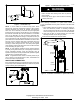
A trap is not necessary on the condensate line. Consult local
codes for additional restrictions or precautions. If local codes
require a trap then the following guidelines are suggested to
assure proper drainage. Install a trap in condensate line of coil
as close to the coil as possible. Make trap at least 3 inches (76
mm) deep and no higher than the bottom of unit condensate
drain opening (See Figure 6). Pitch condensate line 1 inch (25.4
mm) for every 10 ft. of length to an open drain or sump. Make
sure that the outlet of each trap is below its connection to
condensate pan to prevent condensate from overflowing the
drain pan. Prime all traps, test for leaks, and insulate traps and
lines if located above a living area.