
Installation Manual
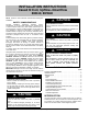

6 484 01 3601 02
Specifications subject to change without notice.
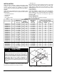
3” / 76mm
A08067
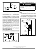
Figure 6 − Condensate Trap
NOTE: If unit is located in or above a living space, where
damage may result from condensate overflow, a field−supplied,
external condensate pan should be installed underneath the
entire unit, and a secondary condensate line (with appropriate
trap) should be run from the unit into the pan. Any condensate in
this external condensate pan should be drained to a noticeable
place. As an alternative to using an external condensate pan,
some localities may allow the running of a separate 3/4 inch (19
mm) condensate line (with appropriate trap) per local code to a
place where the condensate will be noticeable. The owner of the
structure must be informed that when condensate flows from
secondary drain or external condensate pan, the unit requires
servicing or water damage will occur. To further protect against
water damage, install a float switch to shut the unit off if the water
in the secondary pan gets too high.
NOTE: To avoid drainage problems, test the primary drain line
by slowly pouring water into the pan. Check piping for leaks and
proper condensate drainage. Using the secondary drain as
explained in the previous note provides further protection against
overflow due to a clogged primary drain.
NOTE: In applications where return air humidity levels stay at
70% or above for a prolonged period of time, condensation can
form on the bottom of pan and drip.
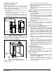
WASTE LINE CONNECTION
If the condensate line is to be connected to a waste (sewer) line,
an open trap must be installed ahead of the waste line to prevent
escape of sewer gases (See Figure 7).
A10216
Figure 7 − Condensate Drain to Waste Line
EXPLOSION HAZARD
Failure to follow this warning could result in personal
injury or death.
Provide trap with air gap in drain line when connecting
to waste (sewer) line.
!
WARNING
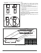
Humidifier Application
When installing a humidifier in a system which contains an
N−coil, consideration must be given to location of coil slabs. See
Figure 8.
1. The humidifier should be mounted to the supply plenum or
return duct whenever possible. If necessary, humidifiers
can be mounted to the left side of coil casing. The right side
of the coil casing must not be used to mount the humidifier.
2. Care must be taken to prevent damage of N−coil when
attaching humidifier to coil casing or plenum.
3. Ensure that humidifier has adequate airflow.
Supply
Evaporator
Upflow
Furnace
N−Coil
A05414
Figure 8 − Installation of Humidifier in System with N−Coil
Copyright 2017 International Comfort Products
Lewisburg, TN 37091 USA