
Installation Manual


18 440 01 4501 01
Specifications subject to change without notice.
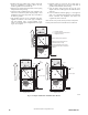
UPFLOW DOWNFLOW HORIZONTAL
YES
NO
NO
YES
YES
YES
NO
120°
MIN
YES
120°
MIN
YES
120°
MIN
90°
90°
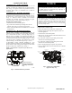
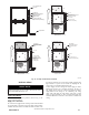
PERFORATED
DISCHARGE DUCT
FLANGE
A10493
Fig. 19 -- Duct Flanges
Return Air Connections
FIRE HAZARD
A failure to follow this warning could cause personal injury,
death and/or property damage.
Never connect return--air ducts to the back of the furnace.
Follow instructions below.
!
WARNING
The return--air duct must be connected to bottom, sides (left or
right), or a combination of bottom and side(s) of main furnace
casing. Bypass humidifier may be attached into unused return air
side of the furnace casing. See Fig. 22, 23, and 24.
Bottom Return Air Inlet
These furnaces are shipped with bottom closure panel installed in
bottom return-- air opening. Remove and discard this panel when
bottom return air is used. To remove bottom closure panel, see Fig.
27 and 28.
Side Return Air Inlet
These furnaces are shipped with bottom closure panel installed in
bottom return --air opening. This panel MUST be in place when
only side return air is used. Where required by code, seal bottom
closure to furnace with tape, mastic or other durable sealing
method.
NOTE: Side return --air openings can be used in UPFLOW and
some HORIZONTAL configurations. Do not use side return--air
openings in DOWNFLOW configuration. See Fig. 22, 23, and 24.
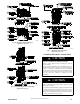
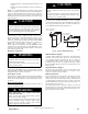
Leveling Legs (If Desired)
In upflow position with side return inlet(s), leveling legs may be
used. See Fig. 20. Install field-- supplied, 5/16 x 1 -- 1/2 in. (8 x 3 8
mm) (max) corrosion--resistant machine bolts, washers and nuts.
NOTE: Bottom closure must be used when leveling legs are used.
It may be necessary to remove and reinstall bottom closure panel to
install leveling legs. To remove bottom closure panel, see Fig. 27
and 28.
To install leveling legs:
1. Position furnace on its back. Locate and drill a hole in each
bottom corner of furnace.
2. For each leg, install nut on bolt and then install bolt with
nut in hole. (Install flat washer if desired.)
3. Install another nut on other side of furnace base. (Install flat
washer if desired.)
4. Adjust outside nut to provide desired height, and tighten in-
side nut to secure arrangement.
5. Reinstall bottom closure panel if removed.
1
3
/
4
1
3
/
4
1
3/
4
1
3/
4
5/
16
5
/
16
5/
16
5/
16
(44mm)
(8mm)
(44mm)
(8mm)
(8mm)
(8mm)
(44mm)
(44mm)
A89014
Fig. 20 -- Leveling Legs
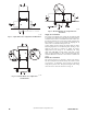
Downflow Installation
NOTE: The furnace must be pitched as shown in Fig. 21 for
proper condensate drainage.
Supply Air Connections
NOTE: For downflow applications, this furnace is approved for
use on combustible flooring when any one of the following
accessories are used:
S Special Base, NAHA01101SB
S Cased Coil Assembly Part No. EAM4X, END4X, ENW4X,
EAD4X
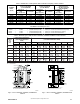
1. Determine application being installed from Table 8.
2. Construct hole in floor per Table 8 and Fig. 29.