C AIR CONDITIONER USER'S MANUAL HSC-24A MODEL : HSC(O)-24A HSCO-24A ▶ Thank you for purchasing the unit. Before operation please read this user’s manual carefully. ▶ It is essential that you read ‘SAFETY INSTRUCTIONS’ carefully before use and follow them at all times. ▶ Keep this manual on hand for reference. ▶ The warranty form is on the last page. Please complete it now and keep it in a safe place. ▶ This unit is specified for use on the rated voltage power supply.
TABLE OF CONTENTS ■ SAFETY INSTRUCTIONS 3~4 ■ GENERAL ADVICE BEFORE USE 4 ■ EXTERIOR DESCRIPTION 5 ■ SPECIFICATIONS 6 ■ CONTROL PANEL FUNCTIONS 7 ■ MODE CHANGING METHOD 8 ■ HOW TO SET THE 'OFF' TIMER 9 ■ TEMPERATURE CONTROL OPERATION 10 ■ SELECTION 11 ■ 'ERROR' and WARNING INDICATORS 12 ■ FIRE ALARM & ERROR SIGNAL CONNECTION 13 ■ ECONOMIC MODE & TROUBLE SHOOTING 14 ■ CLEANING AND MAINTENANCE 15 ■ ACCESSORIES 16 ■ WARRANTY 20 The following instructions are to ensure user’s safe
SAFETY INSTRUCTIONS WARNING Use a circuit breaker for the capacity. (It may cause fire and electric shock) The following symbols are for your guidance: Before cleaning, disconnect the unit. (Otherwise risk of electric shock) = You must NOT. = You MUST. Do not use a damaged power cable. (Short, fire or shock hazard) Do not use an extension lead unless of the approved type. (Risk of fire and / or electric shock) Do not place anything on top of the machine.
SAFETY INSTRUCTIONS CAUTION Do not place this unit on uneven, unstable or inclined surface. (This could cause malfunction) When storing this unit, keep it in a dry, cool place. (To prevent corrosion and malfunction) If not being used for some time or if lightening is present, always disconnect from power. (To prevent risk of electric shock, short circuit or fire) Do not spray water onto this unit nor use solvents such as benzene, thinner or alcohol for cleaning.
EXTERIOR DESCRIPTION FRONT VIEW ① ① ① Cool Air Outlet ② ② ② Handle ③ ③ ③ Digital Controller ④ ④ ④ Electrical Access panel ⑤ Power Plug ⑤ ⑤ ⑥ ⑥ ⑦ ⑦ ⑥ Fire Alarm Connection Port ⑦ Casters (Front Lockable) BACK & SIDE VIEW ① ① ① Top Fan / Wiregrille ② Evaporator Filter Ambient Air Intake ② ③ ② ③ ④ ④ Water Level Indicator to Check water Level of the Condensate Tank ⑤ ⑤ Condensed Water Tank to collect water generated during cooling ④ ⑤ ③ Condenser Filter 5
SPECIFICATIONS MODEL HSC(O)-24A Cooling capacity Btu/h (W) 23,500 (6,900) Power Supply - 220Vac 60Hz 1Ph Power Consumption kW 2.74 Current Consumption A 12.6 MAX gal/day 22.8 AHAM gal/day 15.9 Refrigerant lb R-410A / 2.97 Dimensions (WxDxH) inch 19.3 x 23.6 x 51.3 Weight Ib 210 Moisture Removal Cooling 65˚F DB 60%RH ~ 113˚F DB40%RH Dehumidifier 59˚F DB 60%RH ~ 113˚F DB40%RH Operating Range Nema Plug LCDI 6-20 ※When operating at less then 72℉, the A.F.
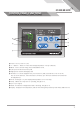
CONTROL PANEL FUNCTIONS ⑧ ⑦ ⑧ ⑨ ⑩ ⑪ ⑤ ⑥ ④ ③ ① ② ① Power : Use to power on / off. ② ∨ ∧ Button : Raises or lowers the setting temperature or sleep (off) time. ③ Mode : Use to select Cooling / Fan / Dehumidifier mode. ④ Low Speed : Controls fan low speed. ⑤ High Speed : Controls fan high speed. ⑥ Off Timer : To set the length of time, once turned on, that you wish the cooler to run for. You can set 0~24 hours. Time intervals are 30 mins. up to 10 hours and then 1 hour between 10 and 24 hours.
MODE CHANGING METHOD CO ※ COOLING MODE If you press 'Mode' button. 'COOL' is displayed. then LED is on. OL FA ※ FAN MODE When the cooling is operating. If you press the 'Mode' button, 'FAN' is displayed. then LED is off. ※ DEHUMIDIFICATION MODE When the fan is operating, If you press the 'Mode' button. 'DEHU' is displayed. then LED is on.
HOW TO SET THE ‘OFF’ TIMER This function enables you to set the length of time you want the unit to operate. You can set the time period from 30min. to 24 hours in 30min. and 1 hour increments. 1. When unit is operating, press the 'Off Timer' button and set the length of time you want by pressing ∧ or ∨. Each time you press the button you will increase the 'time to off' period by 30mins. up to 10 hours, and 1 hour up to 24 hours. The display will show 5 for 30min and 1 for an hour.
TEMPERATURE CONTROL OPERATION •When you turn ON, the setting temperature is displayed. 79 •You can change setting temperature. •The display showing the set temperature will blink 3 times. Display Room Temperature range & Setting range. COOLING MODE Mode Display range Setting range Room 32℉ ~ 99℉ 64℉ ~ 86℉ Cooling operates when Room temperature is more than set temperature. Cooling stops when Room temperature is less than set temperature.
SELECTION SPOT or ROOM MODE To change the temperature of the entire room, select Spot or Room mode. For 'targeted' cooling of machinery servers or people etc select 'spot mode'. Applicable only when cooling mode. • If you want to display room temperature, when unit is operated, push 'mode' and '∨' button simultaneously for 3 seconds. • Light be on the 'Room LED' when room mode set. LOCK or UNLOCK • If you press '∨' for 5 seconds when the unit is 79 79. turned off you can control 'LOCK, UNLOCK' mode.
‘ERROR’ and WARNING INDICATORS Error Code Problem Corrective Action High pressure Blocked air filter Blocked / kinked exhaust duct Ambient temperature is too high Ensure exhaust duct is not blocked / kinked Do not use the air conditioner if ambient temperature is higher than 113℉ Low pressure Verify Electrical Clean Filters and Coils Verify Power (Voltage/Amps) Check Filters Evaporator/Condenser Check Evaporator/Condenser Coils Check refrigerant level and/or refrigerant leak.
FIRE ALARM & ERROR SIGNAL CONNECTION FIRE ALARM Input Terminal FA1 and FA2 When the signal from the fire alarm system is received, the unit turns off and does not operate until the unit has been RESET. Connecting the fire alarm wire from fire alarm system 1. Remove 'Cap' and the 'Fire Alarm cover'. 2. Use recommended fire alarm wire size from 16 AWG to 26 AWG for a solid wire, or 16 AWG to 22 AWG for a stranded wire with ring terminal for #5 stud size. 3. Connect fire alarm to terminal FA1 and FA2.
ECONOMIC MODE Cond. Fan Evap. Fan economic mode button Model Economy Normal Economy Normal Etc. (3 sec. continuous) HSC-12L - - Stop after 30 sec. Run airflow HSC(O)-14/18 Stop Run Stop after 30 sec. Run airflow (High) HSC(O)-24A Stop Run Stop after 30 sec. Run airflow (High) HWC-19 Stop Run Stop after 30 sec. Run airflow (High) HSC(O)-36B Stop after 1 min. Stop after 1 min. Stop after 1 min. Run ▲ (UP) HSC(O)-60 Stop after 1 min. Stop after 1 min. Stop after 1 min.
CLEANING AND MAINTENANCE CLEANING THE AIR FILTERS 1. To remove filters, slide up a little ① and pull towards you ②. 2. Clean the filters with water or compressed air. 3. Clean evaporator and condenser units with a vacuum cleaner or compressed air. MAINTENANCE 1. After cleaning, completely dry the inside of the unit by operating on 'Fan Mode'. 2. Turn "OFF" at control panel, remove plug from socket. Coil and store cable neatly. 3.
ACCESSORIES 16
MEMO 17
MEMO 18
MEMO 19
WARRANTY (Applicable to first retail purchaser only) AIRREX unit gives the more reliable performance, comfort and durability the more they are used. They are built under a strict quality assurance regime which includes inspection both during and after production and exhaustive reliability testing. In the unlikely event you have any problems, please contact your dealer or distributor.