Oxygen Concentrator Service Manual For VisionAire, VisionAire 2 & VisionAire 3 Models AirSep Corporation · 401 Creekside Drive · Buffalo, NY 14228-2085 USA Telephone: (716) 691-0202 · 24-Hour Fax: (716) 691-4141 · www.airsep.
____________________________________________________________________________________ Expedited Product Warranty Check service is always at your fingertips with AirSep: http://www.airsep.com/medical/equipmentproviders.html OR In the US or Canada, dial 866-873-9277 AirSep® is a registered trademark of AirSep Corporation. • VisionAire™ is a trademark of AirSep Corporation.
Table of Contents Section 1.0 Introduction 1.1 Equipment Provider Responsibility 1 1.2 Important Notice and Symbol Explanations 2 1.3 Functional Specifications 5 2.1 Description of Operation 6 2.2 Operation Check 6 2.3 Alarm System 6 2.3.1 2.3.2 2.3.3 7 7 7 Section 2.0 Operation Check and Oxygen Concentration Test Start Up Power Failure Alarm Test No Flow Alarm Test 2.4 Oxygen Concentration Test and Specification 7 3.1 Instructions 8 3.
.3.2 4.4 4.5 4.6 4.7 4.8 Capacitor Replacement 12 Solenoid Valves 12 4.4.1 4.4.2 12 14 Valve Manifold Replacement Solenoid Valve Coil Replacement Sieve Beds 14 4.5.1 14 Sieve Bed Replacement Cabinet Fan 15 4.6.1 15 Cabinet Fan Replacement Circuit Board 16 4.7.1 17 Circuit Board Replacement Product Regulator Check and Setting 18 4.8.1 18 4.8.2 4.8.3 4.8.
Section 5.0 Troubleshooting 5.1 Operation Pressure Test 26 5.1.1 5.1.2 26 26 High Operating Pressure Low Operating Pressure 5.2 General Troubleshooting 27 5.3 Troubleshooting Chart 28 5.
Appendix Exploded Drawings Wiring Diagram - VisionAire A Wiring Diagram – VisionAire 2, VisionAire 3 B Valve Wire Harness – WH105-1 C Main Assembly D Center Section Assembly E Compressor Enclosure Assembly F Compressor Assembly G Valve Manifold Assembly H vi MN138-1 Rev H 02/14
1.0 Introduction 1.1 Equipment Provider Responsibility All Equipment Providers of the VisionAire™ Oxygen Concentrator must assume responsibilities for handling, operational check-out, patient instruction, and oxygen concentration checks. These responsibilities are outlined below and throughout this manual. As an Equipment Provider, you must do all of the following: § Inspect the condition of each VisionAire unit immediately upon delivery to your business location.
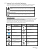
1.2 Important Notice and Symbol Explanations As you read the manual, pay special attention to the WARNING, CAUTION, and NOTE messages. They identify safety guidelines or other important information as follows: Describes a hazard or unsafe practice that can result in severe bodily injury or death. Describes a hazard or unsafe practice that can result in minor bodily injury or property damage. Provides information important enough to emphasize or repeat.
Symbol Description Symbol Consult the accompanying documents Description Keep unit and accessories dry Proper disposal of waste of electrical and electronic equipment required Use no oil or grease Oxygen outlet connection to the cannula Caution: Federal law (USA) restricts this for sale or rental by or on the order of a physician or licensed health care provider.
Classification Type of protection against electric shock: Class II Protection from electric shock is achieved by DOUBLE INSULATION. Protective earthing or reliance upon installation conditions is not required. Degree of protection against electric shock: Type B Equipment providing a particular degree of protection against electric shock, particularly regarding: 1) allowable leakage current; 2) Reliability of protective earth connection (if present). Not intended for direct cardiac application.
1.3 Functional Specifications Oxygen Concentration: 1-5 liters per minute at 90% +5.5/-3% 1-3 liters per minute at 90% +5.5/-3% (VisionAire 3) ⅛-2 liters per minute at 90% +5.5/-3% (VisionAire 2) (Based on 70°F [21°C] at sea level) Accuracy: ± 10% of indicated flow setting, or ± 200 ml, whichever is greater. Response Time: Allow 5 minutes to attain maximum oxygen concentration. Positioning: Operate the unit in an upright position, maintaining at least 12 inches (30.
2.0 Operational Check and Oxygen Concentration Test 2.1 Description of Operation Air is drawn into the VisionAire Oxygen Concentrator. For overall, sound efficiency, before air enters the compressor, it passes through the unit’s intake muffler. Pressurized air then exits the compressor and moves to the valve manifold. The valve manifold incorporates the use of five two-way solenoid valves which control the flow of air and oxygen in and out of the molecular sieve beds.
VisionAire Intermittent Alarm Indicators Condition Audible Alarm No Power One beep Low O2 Two beeps Low Pressure Three beeps High Pressure Four beeps High Temperature Five beeps No Flow Six beeps If the high pressure alarm is activated, the compressor and valves will shut down, and the audible four–beep alarm will continue. This alarm remains on until you set the I/0 power switch to the “0” position. Refer to Section 5.0 for alarm identifications, and a list of probable alarm causes. 2.3.
3.0 General Instructions 3.1 Instructions It is important that patients thoroughly understand how to operate the AirSep VisionAire unit. This enables proper treatment as prescribed by a qualified, licensed health care provider/physician. If patients experience any discomfort or the unit alarms, they must notify their licensed health care provider/physician immediately. You, as the Equipment Provider, are responsible to see that each patient receives the Patient Manual.
Do not use liquid directly on the unit. Clean the exterior of unit and power cord only with a mild household cleaner applied with a damp cloth or sponge, and then wipe all surfaces dry. 3.2 Patient, Provider, and Routine Maintenance AirSep does not require any preventative or routine maintenance on the VisionAire concentrator. VisionAire’s unique design and technology allows for a virtually maintenance-free oxygen concentrator.
4.0 Main Components 4.1 Components The design of the VisionAire Oxygen Concentrator allows for easy access and removal of most components. This allows you to perform repair and replacement of parts with minimal time and effort. To prevent accidental electric shock or burn, be sure to set the unit’s I/0 power switch to the “0” position and unplug the power cord of the unit from the electrical outlet before you service the VisionAire Oxygen Concentrator.
Sound Level The condition of the compressor’s cup seals, bearings, and other components can result in an increased sound level. If the compressor’s cup seals or bearings wear to the point that they become noisy, the concentrator may become noticeably louder, therefore compressor service or exchange may be required. 4.3.1 Compressor Replacement Some internal components, including the compressor may require cooling down before component removal. Care should be taken when removing all components.
4.3.2 Capacitor Replacement The capacitor starts the compressor. If the compressor cannot start, the capacitor may be defective and require replacement. To replace the capacitor, follow the steps below: 1. Set the unit’s I/0 switch to the “0” position and unplug the power cord. 2. Remove front panel and locate capacitor. 3. Gently slide entire compressor enclosure towards you to allow easier access to the capacitor.
attached to coils for easier installation. ( Please refer to the Valve Wire Harness drawings WH105-1 located on page C in the Appendix section of this manual as needed) Care must be taken when removing and installing valve coil retainer clips. 10. Using 1/8-inch Allen wrench, remove mounting bolt securing the manifold to the center section. Remove manifold assembly from compressor enclosure. 11.
7. 8. 9. 10. a. Care must be taken not to pinch any wires or tubing between the compressor enclosure and center section before final installation. b. The wire harness for both the left feed valve and the equalization valve, along with the wire harness for the right feed valve, must be routed outside of the valve manifold assembly before connecting to valve coils. c.
Leaks can be so small in air loss that oxygen concentration is not affected immediately. The sieve material can become contaminated gradually. Careful leak testing is important as the sieve material can become contaminated gradually with very small leaks. If replacement is necessary, you must replace both sieve beds at the same time. Sieve Bed Removal To remove sieve beds, follow the steps below: 1. Set the unit’s I/0 switch to the “0” position and unplug the power cord. 2. Remove back panel. 3.
5. Disconnect the wire connectors labeled AC Power and PowerSw from circuit board. (If equipped with an O2 oxygen monitor, also disconnect wire connectors labeled O2 LED and Sensor). 6. With adjusting compressor enclosure (alternating pulling out top and bottom), gently remove the compressor enclosure from the center section of unit by sliding it out through the front. 7. Locate cooling fan at the back of the compressor enclosure.
The Printed Circuit Boards (PCBs) contain components that are sensitive to electrostatic discharge (ESD) and can damage the board if not handled properly. As when handling any ESD-sensitive PCB, observe standard ESD safety procedures. 4.7.1 Circuit Board Replacement Circuit Board Removal To remove the circuit board, follow the steps below: 1. Set the unit’s I/0 switch to the “0” position and unplug the power cord. 2. Remove both front and back panels. 3.
6. Leak test fitting connections of sieve beds. 4.8 Product Regulator Check and Setting The product regulator enables you to set the maximum flow of oxygen output by the VisionAire unit. To check for proper adjustment of the regulator, take the following steps: 1. 2. 3. 4. Set the I/0 power switch to the “I” position. Allow the unit to run for five minutes. Turn the flow meter adjustment knob counterclockwise until it stops (wide open).
When the lockout adjustment is no longer required, follow the normal regulator setting procedure as described in Section 4.8.1. 4.8.3 Back Pressure Correction at Maximum Flow Rate In some cases, additional lengths of oxygen tubing with a humidifier bottle can increase back pressure and limit oxygen flow below the maximum flow setting. To achieve full maximum flow setting, use the following procedure: 1. Plug in the unit. 2.
8. With the spring behind the seat, screw the diaphragm stem guide back into the body of the regulator. (Do not over tighten.) 9. Install a clean or replacement diaphragm. 10. Put the large spring and slip ring into the bonnet, and screw the bonnet onto the regulator body. 11. Reset the product regulator as described in Section 4.8.1. 4.9 Circuit Breaker Replacement Circuit Breaker Removal To remove the circuit breaker, follow the steps below: 1.
4.11 Hour Meter Replacement FOR P/N: HM009-2 ONLY: HM009-2 is a dual timer hour meter. To toggle between the two display screens - press the pinhole reset switch once to display “TMR1” mode. To reset the timer display – confirm that “TMR1” is displayed in the upper left corner. Press and hold the pinhole reset switch for 3 seconds until 0.0 is displayed. Hour Meter Removal To remove the hour meter, follow the steps below: 1. Set the unit’s I/0 switch to the “0” position and unplug the power cord. 2.
Flowmeter Installation 1. To install a new flow meter, follow the flow meter removal procedure in reverse order. Leak test the tubing connections. 2. Assure flow meter reads ½ liter above the maximum flow rate when fully opened. (Refer to section 4.8 Product Regulator Check and Setting for proper adjustment as needed). 3. To avoid the possibility of activating no flow alarm, set flow meter to desired liter flow prior to turning unit off. 4.
4.14 Oxygen Monitor Circuit Board Replacement (In Equipped Units) Oxygen Monitor Circuit Board Removal To remove the circuit board, follow the steps below: Care must be taken when removing and installing tubing to circuit board sensor to prevent damaging sensor. 1. Set the unit’s I/0 switch to the “0” position and unplug the power cord. 2. Remove both front and back panels. 3. When viewing unit from the back, locate oxygen monitor circuit board and remove the tie-wraps at tubing connections. 4.
To replace the exhaust muffler, follow the steps below: 1. Follow steps 1-7 in the Compressor Assembly Removal procedure outlined under section 4.3.1. 2. Locate exhaust muffler assembly in back of compressor enclosure, cut tie-wrap securing it in place. 3. Remove tie-wrap from tubing connection, disconnect tubing. 4. Unscrew the top half (exhaust muffler) from exhaust muffler body. 5.
5. Gently position the entire concentrator on its back and separate the base from the center section. (Power cord is still attached to base.) 6. From the underside of base, secure caster nut (located just above the wheel of caster) using a 1/2-inch combination wrench. 7. While securing the nut, remove the top nut of caster using a 9/16-inch combination wrench. Caster Installation To install a caster, follow the removal steps in reverse order. 1.
5.0 Troubleshooting 5.1 Operating Pressure Test Testing the operating pressure is a useful diagnostic tool when a concentrator has low oxygen concentration and requires servicing. Units functioning normally do not require operating tests. Use the following procedure to test the operating pressure of the unit: 1. Set the unit’s I/0 power switch to the “0” position, and unplug the power cord. 2. Remove the front panel of unit. 3.
• • • Check compressor intake path for obstruction. Clean/remove obstruction and verify normal operating pressure returns. An improperly operating circuit board or solenoid valve. Confirm that the circuit board and solenoid valve function properly. A leak in the unit, which allows system pressure to escape. Leak test unit. A compressor with reduced output.If it is below specifications, replace or repair the compressor. 5.
5.3 Troubleshooting Chart Problem Unit does not run. I/0 power switch in “I” position. Compressor runs with intermittent alarm. Oxygen concentration at max flow rate is within specifications. Compressor runs and shuts down periodically. Only start up alarm activates Compressor runs and shuts down periodically with 5-beep intermittent high temperature alarm. Probable Cause • • • • • • • • • • Check wall outlet for power. Reset or replace circuit breaker. Check electrical connections.
Problem Probable Cause Solution Faulty electrical connection at waste valve. Faulty solenoid valve coil. (Acceptable rating: 713-837 Ohms) • Repair electrical connection. • • • • Contaminated sieve beds. Faulty circuit board. Faulty relief valve. • Replace valve coil. (Use of an ohmmeter can be helpful to easily determine faulty coil). Replace sieve beds. Replace circuit board. Replace relief valve. Unit alarms with l/0 power switch in “I” position. Circuit breaker repeatedly trips.
Problem Low oxygen concentration. No flow indicated on flowmeter, and 6-beep no flow alarm is activated. Probable Cause Solution • • • Ambient or unit’s temperature is too high. Leak. Reduced air intake (suction) • Restriction in exhaust muffler • • • Contaminated sieve beds Weak compressor. • • • • • • Faulty circuit board. Faulty solenoid valve Flowmeter is turned off. • • • • Regulator is turned off. • • • • • • • Alarm does not sound.
5.4 Tool Kit and Pressure Test Gauge The tools needed for you to properly service the VisionAire unit are listed below: Multi-adjustable pliers, small wire cutters, small needle-nose pliers, slotted-head screwdriver, Phillipshead screwdriver, adjustable wrench, 1/2-inch combination wrench, 7/16-inch combination wrench, 9/16-inch combination wrench, and 1/8-inch Allen wrench. Pressure test adapter. (AirSep p/n: KI257-2).
Appendix Exploded Drawings Wiring Diagram - VisionAire A Wiring Diagram – VisionAire 2, VisionAire 3 B Valve Wire Harness – WH105-1 C Main Assembly D Center Section Assembly E Compressor Enclosure Assembly F Compressor Assembly G Valve Manifold Assembly H MN138-1 Rev H 02/14
WIRING DIAGRAM VISIONAIRE 115V AND 230V A MN138-1 Rev H 02/14
WIRING DIAGRAM VISIONAIRE 2, VISIONAIRE 3 B MN138-1 Rev H 02/14
VALVE WIRE HARNESS C MN138-1 Rev H 02/14
ITEM PART NUMBER DESCRIPTION ITEM PART NUMBER 1 2 3 4 5 6 7 8 9 CA262-1 CA263-1 CA265-2 CA268-1 CA271-1 CA283-1 CA280-1 CA280-2 CA285-1 15 16 17 18 19 20 21 22 23 F0724-1 FA038-1 FM033-2 FM067-1 FM070-1 FM073-1 HM009-2 LA360-1 MI268-1 FITTING, AIR OUTLET FASTENER, RUBBER KEEPER FLOWMETER, 1/4 FITTING FLOWMETER, 1/8 FITTING FLOWMETER, 2 LPM FLOWMETER, (VISIONAIRE 3) HOUR METER LABEL, AIR OUTLET HUMIDIFIER STRAP 10 CA285-2 CABINET, MOUNTING PLATE, SWITCH CABINET, MOUNTING PLATE, FLOWMETER CABINET,
ITEM PART NUMBER 1 2 3 4 5 6 7 BE187-2 BE187-4 CA261-1 CA283-1 CB114-1 FO149-1 RG096-1 DESCRIPTION BEDS, ASSY, SI018-1 (VISIONAIRE, VISIONAIRE 3) BEDS, ASSY, SI015-1 (VISIONAIRE 2) CABINET, HANDLE, PLATE CABINET, CENTER SECTION CIRCUIT BOARD, OXYGEN MONITOR FOAM, HANDLE, PLATE REGULATOR ITEM PART NUMBER 8 9 10 11 12 13 14 SC037-4 SC084-1 SC119-1 TA004-1 TA121-1 TW002-1 TW017-1 DESCRIPTION SCREW, SELFTAP, CABINET HANDLE SCREW, SELFTAP, REGULATOR SCREW, OXYGEN MONITOR TANK, ASSY, VOLUME (VISIONAIRE
ITEM PART NUMBER 1 2 3 4 5 6 7 8 9 10 11 12 AL018-1 CA284-1 CB102-1 CB102-3 CC006-6 CC006-8 CC006-10 F0005-3 FN019-1 FN041-1 FN046-1 FN047-1 DESCRIPTION ALARM, BUZZER CABINET, COMPRESSOR, ENCLOSURE CIRCUIT BOARD, MAIN CIRCUIT BOARD, MAIN (V2, V3) CAPACITOR, 220-240V CAPACITOR, 120V CAPACITOR, 230V FITTING, MUFFLER FAN, 115V (V2, V3) FAN, 115V, VISIONAIRE FAN, 230V, VISIONAIRE FAN, 230V (V2, V3) ITEM 13 14 15 16 17 18 19 20 21 22 23 24 PART NUMBER FO146-1 MO025-1 MU043-1 MU083-1 SC003-3 SC037-4 TW001-3
ITEM PART NUMBER 1 2 3 4 CL035-1 CO416-1 CO416-2 CO416-3 5 CO416-5 6 CO416-6 7 8 CO432-1 F0644-1 9 FI196-1 DESCRIPTION CLAMP, WIRE COMPRESSOR, 115V, 60Hz, 36 STROKE COMPRESSOR, 230V, 50Hz, 44 STROKE COMPRESSOR, 230V, 60Hz, 36 STROKE COMPRESSOR, 230V, 50Hz, 26 STROKE, (VISIONAIRE 2,3) COMPRESSOR, 115V, 60Hz, 26 STROKE, (VISIONAIRE 2, 3) COMPRESSOR, END CAP ASSY FITTING, BRASS, ELBOW FILTER, COMPRESSOR END CAP, EXTERIOR, ASC ITEM PART NUMBER 10 11 12 13 MO027-1 OR032-1 SC123-3 SC133-1 MOUNT,
ITEM PART NUMBER 1 2 3 4 5 6 7 8 9 F0037-4 F0134-1 F0494-1 F0517-1 F0645-1 FO147-1 FO148-1 HA064-1 MA198-1 DESCRIPTION FITTING, BRASS, MULTIBARB, FEED / WASTE FITTING, COMPRESSION, 5/16” FITTING, BRASS FITTING, BRASS, EQ FITTING, SWIVEL HOSE BARB FOAM, FEED, FITTING FOAM, EXHAUST, FITTING HARDWARE, COIL, ECLIP MANIFOLD, VALVE BLOCK ITEM PART NUMBER 10 11 12 13 14 15 16 17 18 OR022-1 SC118-1 TU165-104 TU152-070 TU180-064 TW001-4 TW016-1 TW011-2 VA374-1 DESCRIPTION O-RING, MOUNTING BOLT SCREW, MOUNTI