AS4000 Wireless Local Loop System Demand Assignment System Overview 605-0000-450 Draft Issue 1.
Demand Assignment System Overview 605-0000-450 Draft Issue 1.
Demand Assignment System Overview Preface 605-0000-450 Draft Issue 1.3dr Date 8/02/00 Notice 1. This manual is subject to revision. 2. All rights reserved. 3. Right of modification reserved. 4. This manual is supplied without liability for errors or omissions. 5. No part of this manual may be reproduced or used except as authorised by contract or other written permission. 6.
Demand Assignment System Overview 605-0000-450 Draft Issue 1.
Demand Assignment System Overview Preface 605-0000-450 Draft Issue 1.3dr Date 8/02/00 Safety Instructions - Warnings and Cautions SAFETY 1. Read and follow all warning notices and instructions marked on the product or included in this manual 2. When installed in the final configuration, the product must comply with the applicable Safety Standards and regulatory requirements of the country in which it is installed.
Demand Assignment System Overview Preface 605-0000-450 Draft Issue 1.3dr Date 8/02/00 The Symbol on an Airspan product signifies that it has been certified according to the EMC directive 89/336/EEC. The product fulfils the requirements according to the following standards: EN50082-1 for Immunity. EN55022 Group 1 Class A for the Central Terminal Emissions. EN55022 Group 1 Class B for the Subscriber Terminal Emissions.
Demand Assignment System Overview Preface 605-0000-450 Draft Issue 1.
Demand Assignment System Overview 605-0000-450 Draft Issue 1.
Demand Assignment System Overview ICL 001 605-0000-450 Draft Issue 1.
Demand Assignment System Overview ICL 001 605-0000-450 Draft Issue 1.3dr Date 8/02/00 CHANGE TYPE/DATE PURPOSE PAGES AFFECTED 1.0, June 1998 Initial Document All 1.1, May 1999 Updates to all sections All 1.2, November 1999 Delete ST-V2, delete LCU, add Modular 1.
Demand Assignment System Overview IXL 001 605-0000-450 Draft Issue 1.3dr Date 8/02/00 INDEX TASK LIST PREFACE: Safety Instructions Warnings and Cautions User Response Form ACCESS: ICL, IXL Issue Control List ................................................................................................ ICL-001 Index Task ListIXL-001 GENERAL SYSTEM INFORMATION: GSI Introduction.......................................................................................................... GSI-001 1.
Demand Assignment System Overview IXL 001 605-0000-450 Draft Issue 1.3dr Date 8/02/00 7.1. CDMA Technology........................................................................................... 16 7.2. Demand Assignment.......................................................................................... 17 7.3. Frequency Ranges Supported. ........................................................................... 18 Hardware Overview. ..............................................................
Demand Assignment System Overview IXL 001 605-0000-450 Draft Issue 1.3dr Date 8/02/00 Figure 7. Demand Assigned Air-Interface Structure GSI-003 Figure 8. The AS4000 Omni-Directional Antenna System (typical) Figure 9. 65°Directional Antenna Figure 10. 180°Directional Antenna Figure 11. AS4000 DA CT Equipment Racks (covers removed) Figure 12. Modem Shelf with front covers removed Figure 13. RF Combiner Shelf Figure 14 Alarm and Breaker Panel GSI-004 Figure 15.
Demand Assignment System Overview IXL 001 605-0000-450 Draft Issue 1.
Demand Assignment System Overview IXL 001 605-0000-450 Draft Issue 1.
Demand Assignment System Overview 605-0000-450 Draft Issue 1.
Demand Assignment System Overview GSI 001 605-0000-450 Draft Issue 1.3dr Date 8/02/00 INTRODUCTION 1. General Purpose of Document The purpose of this document is to familiarise the reader with the features of the AS4000 Demand Assignment Wireless Fixed Access System, sufficient to obtain a good, general understanding of its design, operation, implementation and maintenance principles. 2.
Demand Assignment System Overview 605-0000-450 Draft Issue 1.
Demand Assignment System Overview GSI 002 605-0000-450 Draft Issue 1.3dr Date 8/02/00 SYSTEM OVERVIEW 1. AS4000 Overview The AS4000 Wireless Fixed Access System is a digital point to multipoint radio access system providing wireless access for fixed subscribers to the telecommunication network.
Demand Assignment System Overview GSI 002 605-0000-450 Draft Issue 1.3dr Date 8/02/00 THE SWITCH SITE MANAGEMENT SITE Sitespan Server Sitespan Client To PSTN Access Concentrator SUBSCRIBER SITES NxE1 (e.g. Fibre, P- P Microwave) Antenna (External) Antenna RADIO SITE Service Interface Unit (Internal) Antenna (External) Service Interface Unit (Internal) Central Terminal Racks Figure 1.
Demand Assignment System Overview GSI 002 605-0000-450 Draft Issue 1.3dr Date 8/02/00 The Central Terminal (CT) comprises at least one rack with a RF Combiner Shelf and associated Modem Shelf(s). A CT rack will provide two modem shelves and an RF Combiner Shelf. An Expansion Rack provides for two further modem shelves. All four modem shelves utilise the RF Combiner Shelf in the CT Rack to provide the radio interface.
Demand Assignment System Overview GSI 002 605-0000-450 Draft Issue 1.3dr Date 8/02/00 high rate channels to be split into multiple lower rate channels. Downlink traffic is time division multiplexed into radio channels of 160 kbit/s. On the uplink, overlay codes are applied so that multiple lower rate traffic channels may be code division multiplexed into a single 160 kbit/s radio channel. The DA radio interface utilises protocols that allow efficient access to radio resources.
Demand Assignment System Overview GSI 002 605-0000-450 Draft Issue 1.3dr Date 8/02/00 Specifications for Basic Teleservices are: I.240 Definition of Teleservices (Blue Book) I.241 Teleservices supported by an ISDN. Telephony Part 1, Telefax 4 Part 3, Mixed Mode Part 4 ETS 300 111 Circuit Mode Teleservice Telephony 3.
Demand Assignment System Overview GSI 002 605-0000-450 Draft Issue 1.3dr Date 8/02/00 1.5. Data Services Support Data rates up to 56kbit/s in the voice band using the 64kbit/s codec, and 9.6kbit/s using the 32kbit/s ADPCM codec. Bit error rates Typically better than 10-6. One way system delays are below 10ms, having a minimal impact on data applications. The STs support ISDN, RS-232 and / or 10baseT interfaces.
Demand Assignment System Overview GSI 002 605-0000-450 Draft Issue 1.3dr Date 8/02/00 2. The Central Terminal The Central Terminal (CT) is the AS4000 Base Station. This is deployed in omni or sectored cell configurations supporting variable numbers of Subscriber Terminals (ST) per cell. The CT is a multi-service platform hosting single and dual line telephony, multi-line telephony, digital data leased lines and ISDN basic rate interfaces.
Demand Assignment System Overview GSI 002 605-0000-450 Draft Issue 1.3dr Date 8/02/00 The Central Terminal consists of the following components: 2.1. The Antenna and Feeder sub-system The antenna and feeder sub-system consists of either a two stacked dipole -high gain omni-directional antenna, a 65°directional antenna or a 180°directional antenna assembly mounted on a pole or mast and low-loss coaxial feeder cables which connect the antennas to the CT equipment rack. 2.2.
Demand Assignment System Overview GSI 002 605-0000-450 Draft Issue 1.3dr Date 8/02/00 CT Rack Expansion Rack Alarm and Breaker Panel RF Combiner Shelf Modem Shelf 1 Modem Shelf 3 Modem Shelf 2 Modem Shelf 4 Figure 3. Central Terminal Racks 2.3. Central Terminal Expansion Rack The Central Terminal Expansion Rack connects to the Combiner Shelf in the DA Rack and contains: 2.3.1. Modem Shelves The Expansion Rack accommodates up to two modem shelves.
Demand Assignment System Overview GSI 002 605-0000-450 Draft Issue 1.3dr Date 8/02/00 3. The Access Concentrator The Access Concentrator (AC) is required when AS4000 is operating in “Demand Assigned” mode to de-multiplex the traffic concentrated on the air-interface for presentation to the network switching equipment. The Access Concentrator provides CAS, V5.1 or V5.2 network interface with the Local Exchange.
Demand Assignment System Overview GSI 002 605-0000-450 Draft Issue 1.3dr Date 8/02/00 4. Subscriber Terminals The AS4000 Subscriber Terminal (ST) portfolio includes subscriber terminal types: for Voice, Data, and ISDN. In general, the customer has access to the same range of facilities that are supported by a conventional copper pair.
Demand Assignment System Overview GSI 002 605-0000-450 Draft Issue 1.3dr Date 8/02/00 4.1. The Subscriber Terminal Installation The majority of the electronics is in Service Interface Unit located inside the customer premises. This is connected to the outdoor unit by an IF drop cable. Internal ST (ST-R, S, B, N and M classes) Note The appearance of the Service interface Unit depends on the class (ST- R2 shown) Antenna I/F Drop Cable Service interface Unit Phones Figure 5.
Demand Assignment System Overview GSI 002 605-0000-450 Draft Issue 1.3dr Date 8/02/00 large obstructions in proximity to and in line of sight from the ST to the Antenna. See the ST installation and commissioning manual for deployment rules. The Antenna unit contains a flat plate antenna and a Low Noise Amplifier (LNA). It connects to the IF Drop cable using an F type connector. Power for the LNA is provided via the drop cable. 4.3.
Demand Assignment System Overview GSI 002 605-0000-450 Draft Issue 1.3dr Date 8/02/00 Generic Subscriber Terminal M8/64 M16 Service Interface Unit Type Qty Construction MU-V2 4 Modular Unit in Modular Enclosure MU-V4 4 Modular Unit in Modular Enclosure Function Eight line voice 64kbit/s PCM / 32 kbit/s ADPCM Sixteen line voice 32kbit/s ADPCM Table 1. AS4000 DA Subscriber Terminals General Note: 32kbit/s ADPCM voice services available for Subscriber Terminal hosted on Demand Assigned Modem shelves. 5.
Demand Assignment System Overview GSI 002 605-0000-450 Draft Issue 1.3dr Date 8/02/00 6. System Interfaces Interfaces between the various elements of the AS4000 system are as follows: 6.1. AC Management Interface The AC provides up to two asynchronous ports for connection to a management system. These ports will carry all management information for the AC and all dependent CTs that do not have independent management communications.
Demand Assignment System Overview GSI 002 605-0000-450 Draft Issue 1.3dr Date 8/02/00 All signalling is digital using either Channel Associated Signalling (CAS) or Common Channel Signalling (CCS) protocols. AS4000 DA interfaces to digital switching systems that have 2Mbit/s subscriber ports. Support for 2 wire VF interfacing is via external channel bank equipment, such as Alcatel’s LS-120. • Channel Associated Signalling. Support for timeslot 16 ABCD bit CAS is provided.
Demand Assignment System Overview GSI 002 605-0000-450 Draft Issue 1.3dr Date 8/02/00 7.2. Demand Assignment The “Demand Assigned” Radio interface makes a temporary call by call assignment of channels, to Subscriber Terminals in residential telephony applications, where the per line traffic allows the provision of Graded Service. The radio interface differs in that links are allocated as either Traffic, or Control channels. RF1 to 4 3.
Demand Assignment System Overview GSI 002 605-0000-450 Draft Issue 1.3dr Date 8/02/00 STs track available TCHs to permit “fast acquisition”. When a user’s line goes “offhook”, STs request allocation of a TCH from the available pool. The CT instructs STs to “seize” a particular TCH, if access noise permits.
Demand Assignment System Overview GSI 003 605-0000-450 Draft Issue 1.3dr Date 8/02/00 CENTRAL HARDWARE OVERVIEW 8. Antenna and Feeder Sub-system 8.1. General Description The antenna and feeder sub-system consists of a high-gain omni-directional antenna assembly and low-loss coaxial feeder cables which connect the antennas to the CT equipment rack. To ensure the antenna assembly is above roof height and has an unobstructed view of the horizon, an antenna mast may be employed.
Demand Assignment System Overview 605-0000-450 Draft Issue 1.3dr Date 8/02/00 NOTE: An installation will Consist of two antennae, two feeders and associated kit. Antenna Beam U-Clamps Mounting Pole Earth Point Cold Shrink Feeder Tail Mounting Plate Cold Shrink Feeder Earth Type H Split Bolt Earthing Cable . Feeder Hangers Catenary Feeder Feeder Earth Type H Split Bolt Feed-thru with waterproof gland Wood Pole or Mast Feeder Earth Ground Earth Spike Figure 8.
Demand Assignment System Overview 605-0000-450 Draft Issue 1.3dr Date 8/02/00 Adjustable Bracket Antenna Fixed Bracket N-type Feeder Connections Figure 9. 65°Directional Antenna Adjustable Bracket Antenna Fixed Bracket N-type Feeder Connections Figure 10.
Demand Assignment System Overview GSI 003 605-0000-450 Draft Issue 1.3dr Date 8/02/00 9. Central Terminal (CT) 9.1. General Description The 2.2m high ETSI style AS4000 CT equipment racks containing multiple shelf assemblies. These house the equipment necessary to support from one to 60 customer radio links and from one to four 2Mbit/s CAS or DASS links to the Access Concentrator. (see Figure 11). CT Rack Expansion Rack Alarms and Breakers RF Combiner Shelf 2.
Demand Assignment System Overview GSI 003 605-0000-450 Draft Issue 1.3dr Date 8/02/00 9.3. CT Equipment Rack Shelves: 9.3.1. Modem Shelves Each Modem Shelf terminates one RF Channel, supporting up to 15 radio links, provides an E1 network interface with the Access Concentrator and a V.24 (RS232) Network Management interface to the Sitespan. Redundant E1 links can also be provided to maintain the backhaul link to the Access Concentrator if the main link fails.
Demand Assignment System Overview GSI 003 605-0000-450 Draft Issue 1.3dr Date 8/02/00 SLOT 9 SITESPAN SITESPAN 2 1 SCLAT E5 E5 CABINET RACK CONTROL 55B ALARM BASEBAND SLOT 5 E1IN E1IN COMBINER E1OU T E1OU T BASEBAND RF CAL JTAG COMBINER SCAUX DOOR LED -48VB -48VA AU Spare AU Modem Modem Modem Modem Modem DTU/XTU/CU Modem Spare BATTPOS Spare Spare Spare DTU AUX9 Spare AUX5 SC FAN PSU2 PSU1 -48V Figure 12. Modem Shelf with front covers removed 9.3.2.
Demand Assignment System Overview GSI 003 605-0000-450 Draft Issue 1.3dr Date 8/02/00 In the receive direction, incoming signals from the antenna are extracted, filtered, amplified by the LNA and split among the (up to) four RF Cards and their associated Modem Shelves. The RF Combiner Shelf (see Figure 13) is equipped with: • RF Cards, (up to four) that convert the baseband signal from each modem shelf into a single RF channel in the 2GHz range (and vice versa).
Demand Assignment System Overview GSI 003 605-0000-450 Draft Issue 1.3dr Date 8/02/00 • Three Combiner Shelf PSUs to provide the interface between the local DC power source and the equipment of the AS4000 CT Rack. The shelf contains two circuit breakers, to give protection by using two independent DC supplies, and three PSUs that supply a nominal 13.5V DC. The input to the PSU can be in the nominal range of − 24V to − 60V.
Demand Assignment System Overview GSI 004 605-0000-450 Draft Issue 1.3dr Date 8/02/00 ACCESS CONCENTRATOR HARDWARE OVERVIEW 10. The Access Concentrator The Access Concentrator (AC) is required when AS4000 is operating in “Demand Assigned” mode to de-multiplex the traffic concentrated on the air-interface for presentation to the network switching equipment. Also in system versions using 32kbit/s compression the decompression to 64kbit/s is performed within the AC.
Demand Assignment System Overview GSI 004 605-0000-450 Draft Issue 1.3dr Date 8/02/00 10.1. Power Requirements The rack requires two DC power supplies. The supply can range from -22 Volt to -60 Volt DC. The input current for a fully loaded Access Concentrator Rack is 13 Amps at 22 Volt reducing to 4.7 Amps at 60 Volt (280W). 10.2. AC Equipment Rack Shelves: Up to two AC shelves can be equipped within the AC Rack. Each AC shelf consists of: 10.2.1.
Demand Assignment System Overview GSI 005 605-0000-450 Draft Issue 1.3dr Date 8/02/00 SUBSCRIBER TERMINAL HARDWARE OVERVIEW Located at the customer’s premises, the ST equipment terminates the radio link and provides the interface to the customer premises equipment (CPE) e.g., telephone, facsimile machine, personal computer, modem etc. 11. Subscriber Terminals - Service Interface Units 11.1.
Demand Assignment System Overview GSI 005 605-0000-450 Draft Issue 1.3dr Date 8/02/00 Figure 17. The R Series Service Interface Unit (RU-V2 shown) 11.2. The S Series Sub-Unit Subscriber Terminals The S series Subscriber Terminals are designed for Voice Telephony and use an external antenna and a internal metal box Sub-Unit Service Interface Unit. The unit is designed for use in places where a more robust unit is needed. i.e. Payphones. The STs are powered from the AC mains supply.
Demand Assignment System Overview GSI 005 605-0000-450 Draft Issue 1.3dr Date 8/02/00 Figure 19. The S Series Service Interface Unit. (SU-V2 shown). 11.3. The N Series Subscriber Terminals The N series Subscriber Terminals are designed for Voice Telephony and use an external antenna and an internal Modular Service Interface Unit. The STs are powered from the AC mains supply.
Demand Assignment System Overview GSI 005 605-0000-450 Draft Issue 1.3dr Date 8/02/00 Figure 21. The N Series Service Interface Unit. (MU-V4 shown). 11.4. The B Series Subscriber Terminals The B series Subscriber Terminals are designed for ISDN and use an external antenna and an internal Modular Service Interface Unit. The STs are powered from the AC mains supply. B1 2B+D ISDN line Antenna / RF External Components IF Drop Cable Internal Components Service Interface Unit Socket PSU Figure 22.
Demand Assignment System Overview GSI 005 605-0000-450 Draft Issue 1.3dr Date 8/02/00 Figure 23. The B Series Service Interface Unit. (MU-I shown). 11.5. The L Series Subscriber Terminals The L series Subscriber Terminals are designed for Data and use an external antenna and an internal Modular Service Interface Unit. The STs are powered from the AC mains supply.
Demand Assignment System Overview GSI 005 605-0000-450 Draft Issue 1.3dr Date 8/02/00 The ST-2xL64 supports two 64kbit/s serial data transmissions and operates in Fixed Assigned mode. The Service Interface Unit is MU-D2x64 with 2x 25 way D-Type socket interfaces (RS530). Figure 25. The L Series Service Interface Unit. (MU-D2x64 shown). 11.6.
Demand Assignment System Overview GSI 006 605-0000-450 Draft Issue 1.3dr Date 8/02/00 SYSTEM MANAGEMENT OVERVIEW 12. System Management 12.1. Sitespan Sitespan can manage a range of ACC products (AS4000 Fixed Assigned, AS4000 Demand Assigned, Multiline, and Alcatel Litespan) and is designed to allow the management of these from a central location. Sitespan uses two distinct management elements, a Server to manage the equipment racks, and an Equipment View to provide user access.
Demand Assignment System Overview GSI 006 605-0000-450 Draft Issue 1.3dr Date 8/02/00 Access Concentrator Rack X25 Packet Switched Network or Sitespan Equipment View PC Dialup Modem/ISDN Link or Fixed Link Sitespan Server PC Equipment View Optional Figure 26.
Demand Assignment System Overview Appendix A 605-0000-450 Draft Issue 1.3dr Date 8/02/00 APPENDIX A - RF CHANNEL PLANS AS4000 supports WFA system implementation in various frequency ranges within the ITU-R and ETSI 2GHz and 3GHz frequency ranges. The specific implementations currently available operate in frequency bands at 1.8-1.9Ghz, 2.0-2.3GHz, 2.3-2.5GHz and 3.4-3.6GHz in accordance with the AS4000 “channel plans” shown below. The RF channelisation is 1.5/3.5/4.
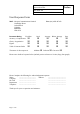
Demand Assignment System Overview Appendix A 605-0000-450 Draft Issue 1.3dr Date 8/02/00 Uplink (ST to CT) − − − F3 F4 F5 F6 F7 F8 F9 F10 fo = 2155 MHz F11 F12 2204.75 2208.25 2211.75 2215.25 2218.75 2222.25 2225.75 2229.25 2232.75 2236.25 2239.75 2243.25 2029.75 2033.25 2036.75 2040.25 2043.75 2047.25 2050.75 2054.25 2057.75 2061.25 2064.75 2068.25 2.0-2.
Demand Assignment System Overview Appendix A 605-0000-450 Draft Issue 1.3dr Date 8/02/00 2243.25 2246.75 2250.25 2253.75 2257.25 2260.75 2264.25 2267.75 2271.25 2274.75 2278.25 2281.75 2068.25 2071.75 2075.25 2078.75 2082.25 2085.75 2089.25 2092.75 2096.25 2099.75 2103.25 2106.75 2.0-2.3GHz Channel Plan 3 fo = 2155 MHz F1 F2 F3 F4 F5 F6 F7 F8 F9F10 F11F12 F1’F2’ F3’F4’F5’F6’ F7’F8’ F9’F10’ F11’ F12’ Uplink (ST to CT) Downlink (CT to ST) 175MHz Duplex Spacing (TX to RX) u CEPT / ERC / Rec.
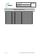
Demand Assignment System Overview Appendix A 605-0000-450 Draft Issue 1.3dr Date 8/02/00 Fo = 3502 MHz F1 F2 F3 F4 F5 F6 F7 F8 F9 F10 F11 F12 3511.75 3515.25 3518.75 3522.25 3525.75 3529.25 3532.75 3536.25 3539.75 3543.25 3546.75 3550.25 3411.75 3415.25 3418.75 3422.25 3425.75 3429.25 3432.75 3436.25 3439.75 3443.25 3446.75 3450.25 3.4-3.6GHz Channel Plan 1 F1’ F2’ F3’ F4’ F5’ F6’ F7’ F8’ F9’ F10’F11’F12’ Uplink (ST to CT) Downlink (CT to ST) 100MHz Duplex Spacing (TX to RX) u CEPT / ERC / Rec.