0 Installing the SPR This chapter describes the installation of the WipLL Subscriber Premises Radio (SPR), located at the subscriber's premises. Warning: Cables with exposed ends (i.e., not yet crimped) should be covered with protective polythene bags during external cable installation processes. Warning: As the system emits microwave radiation, a minimum distance of 200 mm must be maintained from the front of the SPR. However, for the 700 MHz band (i.e.
Installing the SPR Hardware Installation Guide Note: The digital portion of the transceiver has been tested and found to comply with the limits for a Class B digital device, pursuant to part 15 of the FCC rules. These limits are designed to provide reasonable protection against harmful interference in a residential installation.
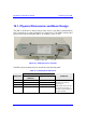
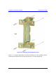
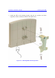
Hardw are Installation Guide Installing the SPR 10.1. Physical Dimensions and Basic Design The SPR is encased in a chassis and provides access to the SPR’s communication port (15-pin D-type) at the front panel (see figure below). The SPR’s bottom panel provides holes for mounting the SPR to, for example, a pole or wall. 15-pin D-type port Figure 10-1: SPR (with built-in antennal) The SPR’s physical dimensions are described in the following table.
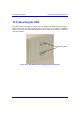
Installing the SPR Hardware Installation Guide 10.2. Mounting the SPR The SPR can be mounted on a wall or pole. The SPR is mounted using the mounting holes located on the SPR’s bottom panel (see Figure 10-2), and the mounting bracket (provided). The mounting brackets for wall- and pole mounting are different from one another. Mounting holes Figure 10-2: SPR bottom panel providing holes for mounting 10-4 Airspan Networks Inc.
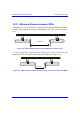
Hardw are Installation Guide Installing the SPR 10.2.1. Minimum Distance between SPRs A minimum of 3-meter separation is required between mounted SPRs and existing customer radio equipment when not transmitting on the same sector (see Figure 10-3). 3.0 metres Figure 10-3: SPR separation when not transmitting on the same sector A 1-meter separation is required between SPRs when on the same sector and transmitting to the same BSR without requiring shielding (see Figure 10-4). 1.
Installing the SPR Hardware Installation Guide 10.2.2. Wall-Mounting SPR wall mounting is performed in two stages: Attaching the mounting bracket to the SPR’s mounting holes. Attaching the mounting bracket (attached to the SPR) to the wall. To mount the SPR on a wall: 1. Position the mounting bracket on the mounting surface (e.g., wall), and then use a pencil to mark the position of the four mounting holes. 2. Drill holes for each hole that you marked in the step above. 3.
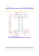
Hardw are Installation Guide Installing the SPR Figure 10-5: Attaching mounting bracket to wall Below is a diagram illustrating the fixing dimensions of the mounting bracket. Ensure that the distance between the hole centers are 120 mm and 60 mm. 02030311-07 Airspan Networks Inc.
Installing the SPR Hardware Installation Guide Figure 10-6: SPR mounting bracket dimensions for the four fixing holes 10-8 Airspan Networks Inc.
Hardw are Installation Guide Installing the SPR 5. Attach the SPR to the mounting bracket using the two stainless steel bolts (supplied), washers, and nuts as shown in the figure below. Figure 10-7: Attaching SPR to mounting bracket 02030311-07 Airspan Networks Inc.
Installing the SPR Hardware Installation Guide Note: Airspan does not provide screws for attaching the mounting bracket to the wall. The screw size depends on the structure of the building to which the bracket is to be attached. When selecting screw sizes, consideration must be given to the weight of the SPR and load that may be induced in windy conditions. 6. Adjust the horizontal positioning of the SPR, and then tighten the two stainlesssteel bolts. Rotation is restricted to the horizontal plane only.
Hardw are Installation Guide Installing the SPR 10.2.3. Pole-Mounting The SPR can be mounted on a pole (see Figure 10-9). Pole mounting allows the SPR to be adjusted in the horizontal as well as the vertical plane. The pole-mounting bracket assembly is designed to support the SPR on a round pole of 45 mm in diameter. Figure 10-9: Mounted SPR 02030311-07 Airspan Networks Inc.
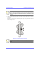
Installing the SPR Hardware Installation Guide To mount the SPR on a pole: 1. Attach the mounting bracket to the SPR using two stainless steel bolts. Locking Holes BSR mounting Bracket Clamping Bracket Pivot Hole ‘U’ Bolt Figure 10-10: SPR mounting bracket assembly 2. Attach the clamping bracket to the mounting bracket using two M8 stainless bolts. 3.
Hardw are Installation Guide Installing the SPR 4. Adjust the vertical position of the SPR. Lock the SPR at the desired position by inserting the locking bolt in the desired position. Once the correct angle has been set both bolts must be tightened to lock the SPR bracket in place. 5. Adjust the horizontal position of the SPR by rotating the SPR about the pole, and then tighten the U-bolt. SPR positioning is obtained in two planes by adjustment of the mounting bracket assembly a shown in Figure 10-11.
Installing the SPR Hardware Installation Guide 10.2.4. Aligning Using the RSS LED Adapter You can align the SPR (or third-party antenna) using Airspan's RSS LED Adapter once the SPR has established a wireless link with the BSR. The RSS LED Adapter indicates the received signal strength (RSS) between the SPR and the BSR. This allows you to accurately position the SPR during installation for optimal radio frequency signal reception. The RSS LED adapter connects between the SPR and SDA by a CAT 5 cable.
Hardw are Installation Guide Installing the SPR 15-pin D-type male connects to SPR side RSSI LED 8 RSSI LED 1 POWER LED 15-pin D-type female connects to SDA side Figure 10-12: RSS LED adapter The following describes the RSS LED adapter's cable setup: Cables: two straight-through cables for SPR-to-RSS LED adapter, and for SDAto-RSS LED adapter.
Installing the SPR Hardware Installation Guide To connect the RSSI LED adapter (see Figure 10-13): 1. Connect the 15-pin D-type male connector, at one end of the straight-through cable, to the SPR. 2. Connect the 15-pin D-type female connector, at the other end of the straightthrough cable from the SPR, to the RSS LED adapter. 3. Connect the 15-pin D-type male connector, at one end of the straight-through cable, to the SDA. 4.
Hardw are Installation Guide Installing the SPR Figure 10-13: Connecting the RSS LED Plug adapter 02030311-07 Airspan Networks Inc.
Installing the SPR Hardware Installation Guide Note: You can connect the RSS LED adapter’s 15-pin male port directly to the SPR’s 15-pin female port, instead of using a cable. Table 10-3 describes the LEDs on the RSS LED adapter.
Hardw are Installation Guide Installing the SPR 10.3. Connecting External Third-Party Antenna (Optional) The SPR model with an N-type connector can be connected to an external antenna. The addition of an external antenna allows greater RF sector coverage than the standard SPR internal antenna models (i.e., 60°). Cable: RF coaxial Connector: N-type male Warning: Before connecting the external antenna, ensure that the SPR is NOT connected to the power source.
Installing the SPR Hardware Installation Guide To connect the SPR to an external antenna: Attach an N-type male connector of the third-party antenna to the N-type receptacle located on the SPR’s front panel. Figure 10-14: SPR model with N-type connector for attaching an external antenna Note: Airspan supplies unterminated cables for N-type connectors. Refer to Appendix B, “Cable Crimping" for N-type cable crimping. 10-20 Airspan Networks Inc.
Hardw are Installation Guide Installing the SPR 10.4. Connecting to the SDA The SPR’s power supply and connectivity to the subscriber’s Ethernet network is provided by the SDA. To connect the SPR to the SDA, you need to connect the SPR’s 15-pin D-type port to the SDA’s 15-pin D-type port using a CAT-5 cable.
Installing the SPR 8 Hardware Installation Guide Sync.- Brown 8 Sync.- Notes: 1) Pins 9 through 15 of the 15-pin D-type connector are not used. 2) The wire color-coding described in the table is WipLL's standard for wire color-coding. However, if you implement your company's wire color-coding scheme, ensure that the wires are paired and twisted according to the pin functions listed in Table 10-4 (e.g., Rx+ with Rx-).
Hardw are Installation Guide Installing the SPR Warning: To avoid electrical shock, before connecting the SPR to the SDA, ensure that the SDA is not connected to the power supply. Notes: 1) The wires are twisted together in pairs, for example, blue/white with blue, and orange/white with orange. This prevents electrical interference between the transmitter pins. For example, pin 3 (Tx+; orange / white) is paired and twisted with pin 4 (Tx-; orange).
Installing the SPR Hardware Installation Guide Figure 10-16: SPR-to-SDA cable connections Note: The maximum cable length permissible between the SPR and SDA is 100 meters. 10-24 Airspan Networks Inc.
Hardw are Installation Guide Installing the SPR 10.5. Connecting to a PC for Serial Configuration To configure an SPR, you need to connect a PC running the WipLL WipConfig configuration tool to the SPR. The SPR’s 15-pin D-type port also provides serial interface to a PC for SPR initial configuration. This port uses 9 of its 15 pins for serial interface; the remaining pins are used for interfacing with the SDA with which the SPR remains connected. To connect the SPR to the management station (i.e.
Installing the SPR Hardware Installation Guide Figure 10-17: Y-cable for serial connection Connector pinouts: Table 10-5: Y-cable SPR-to-SDA connector pinouts SPR 15-pin D-type male 10-26 Pin SDA Function Pin Function 1 0 VDC 1 +48 VDC 2 +48 VDC 2 -48 VDC 3 Ethernet Tx+ 3 Rx+ 4 Ethernet Tx- 4 Rx- 5 Ethernet Rx+ 5 Tx+ 6 Ethernet Rx- 6 Tx- 7 Hop Sync+ 7 Sync.+ 8 Hop Sync- 8 Sync.- Airspan Networks Inc.
Hardw are Installation Guide Installing the SPR Table 10-6: Y-cable SPR-to-PC connector pinouts SPR 15-pin D-type male Pin PC Function Pin Function 12 GND 5 GND 14 RS232 Rx 3 Rx 15 RS232 Tx 2 Tx 9-pin D-type female The Y-cable connector pin assignments are displayed schematically in Figure 10-18. Figure 10-18: Y-cable connector pin assignment 02030311-07 Airspan Networks Inc.
Installing the SPR Hardware Installation Guide To connect the SPR to a PC for serial configuration (see Figure 10-19): 1. Connect the 15-pin D-type male connector, at the one end of the Y-cable, to the SPR. 2. Connect the 15-pin D-type male connector, at the other end of the Y-cable, to the SDA. 3. Connect the 9-pin D-type female (RS232) connector, at the other end of the Ycable, to the PC’s serial port. 10-28 Airspan Networks Inc.
Hardw are Installation Guide Installing the SPR Figure 10-19: SPR cable connections for serial configuration 02030311-07 Airspan Networks Inc.
Installing the SPR Hardware Installation Guide Note: For performing SPR initial configuration using WipLL’s management applications, refer to Airspan’s WipConfig User’s Guide or WipConfig PDA User’s Guide. 10.6. Connecting Power The SPR receives power through its 15-pin D-type port from the SDA. In turn, the SDA connects to an external AC-DC power adapter from where it receives power. The SDA provides 48 VDC nominal power to the SPR (minimum of 30 VDC: maximum of 55 VDC).