
User's Manual Part 2a

Installing the BSR Hardware Installation Guide
4-14 Airspan Networks Ltd. 02030311-05
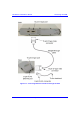
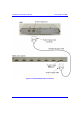
4.5.2. Through the BSDU
For base stations consisting of multiple BSRs, the power supply and connectivity to
the backhaul network is provided by the BSDU. The BSR’s 15-pin D-type port is
connected to the BSDU’s rear panel 15-pin D-type port (labeled BSR #).
Note: For a detailed description of the BSDU, see Chapter 5, “Installing the
BSDU”.
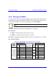
The BSR-to-BSDU cable connection configurations is as follows:
! Connector:
! BSR: 15-pin D-type male (only 8 pins are used)
! BSDU: 15-pin D-type male (only 8 pins are used)
! Cable: straight-through 10Base-T Ethernet 4 Pair Cat 5 outdoor type – 24 AWG
! Connector pinouts:
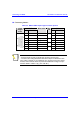
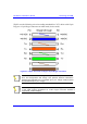
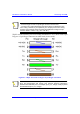
Table 4-4: BSR-to-BSDU 15-pin D-type connector pinouts
BSR BSDU 15-pin
D-type
male
Pin Function
Wire color Wire
pair
Pin Function
1 +48 VDC Blue / white 1 +48 VDC
2 -48 VDC Blue
1
2 -48 VDC
3 Tx+ Orange / white 3 Rx+
4 Tx- Orange
2
4 Rx-
5 Rx+ Green / white 5 Tx+
6 Rx- Green
3
6 Tx-
7 Sync.+ Brown / white 7 Sync.+
8 Sync.- Brown
4
8 Sync.-