
User's Manual Part 2a

Installing the BSR Hardware Installation Guide
4-28 Airspan Networks Ltd. 02030311-05
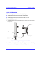
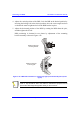
4. Adjust the vertical position of the BSR. Lock the BSR at the desired position by
inserting the locking bolt in the desired position. Once the correct angle has been
set both bolts must be tightened to lock the BSR bracket in place.
5. Adjust the horizontal position of the BSR by rotating the BSR about the pole,
and then tighten the U-bolt.
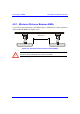
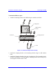
BSR positioning is obtained in two planes by adjustment of the mounting
bracket assembly a shown in Figure 4-18.
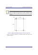
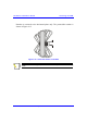
Rotation about the
mounting pole
Rotation about the
mounting bracket
Figure 4-18: BSR GPS orientation in vertical (top figure) and horizontal plane (lower
figure)
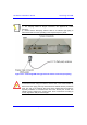
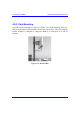
Note: A thread-locking compound is to be used to prevent the bolts working
loose. A loop should be left in the cable for maintenance purposes and to
prevent the cable weight being taken directly on the connector.