
User's Manual Part 2b

Hardware Installation Guide Installing the BSPS
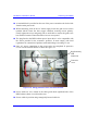
02030311-05 Airspan Networks Ltd. 7-19
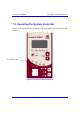
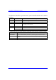
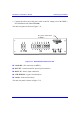
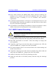
The function of the LED’s provided on the System controller module can be defined
as follows:
LED Color Meaning
AC Green
Input AC voltage is normal
DC Green
Output DC voltage is normal
LVD Red
State of the Low Voltage Disconnect circuit: red indicates that
the battery is disconnected
BATT Green
Battery test has passed
Red continuous General fault alarm
FAULT
Red blinking Faulty rectifier detected
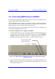
The following lists the buttons and their functions on the System Controller module.
Button Function
BATT TEST
This is a manual battery test button. A pencil tip may be used to activate.
ALARM OFF
This button silences the module internal buzzer. A pencil tip may be used to
activate.
RESET
This button resets the module. A pencil tip may be used to activate.