
User's Manual


1-1
Chapter 1 Overview
This chapter describes the panel function and installation procedure for the
CPE.
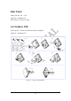
1.1. Indoor CPE
Front Panel LED
Power LED: ON: power on OFF: power fail
LAN LED: ON: connect OFF: disconnect Blinking: data transmit
When the CPE powers on, the LED indicates the CPE states as follow.
Only Red LED is Blinking: synchronization
Only Yellow LED is Blinking: authentication
Only Green LED is Blinking: DHCP client negotiation
After the CPE has connected to the base station, the signal strength LED are
defined as follow.
Only Red LED is ON: the signal is weak. (CINR<8dB)
Yellow LED is ON: the signal strength is medium. (8dB≤CINR<15dB)
Green LED is ON: the signal strength is good. (15dB≤CINR)
Figure 1-1 Indoor CPE Front Panel LED