00
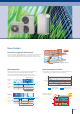
TM AIRSTAGE VRF Systems can be designed to create an air conditioning solution to suit most buildings requirements. AIRSTAGETM VRF Systems can be designed to effectively provide an air conditioning solution from a large domestic residence through to a large scale commercial building.
OUTLINE Fujitsu General provides multi air conditioning systems for buildings AIRSTAGE Series matched to the size and application of the property TM A pleasant air conditioned environment matched to the needs is created by combining a wide variety of outdoor units, indoor units, and controllers.
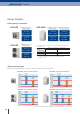
Heat Pump type for heating or cooling operation Heat Recovery type for simultaneous heating and cooling operation Systems for large offices, hotels, and large composite facilities Systems compatible with individual operation mode control, as well as large offices, hotels, and large composite facilities 8HP-48HP 33models • Space saving combination : 8HP to 48HP / 21 models • Energy efficiency combination : 16HP to 44HP / 12 models 8HP-48HP 34models • Space saving combination : 8HP to 48HP / 21 models •
Features Highly Energy Efficiency Efficiency is improved significantly by using DC twin rotary compressor, inverter technology, and large heat exchanger 5 4 8%UP! 3.45 3.2 16%UP! 3.95 3.4 27%UP! 4.07 18%UP! 27%UP! 3.94 4.37 3.7 3.2 16%UP! 4.3 3.71 3.
More Comfort ±0.5ÛC High Precision refrigerant flow control . Set temp Hot Precise and smooth refrigerant flow control is achieved by using a DC Inverter control in conjunction with individual indoor unit electronic expansion valve control. This allows high precision comfortable temperature control of ±0.5°C.
Features Design Flexibility High capacity connection AIRSTAGE J-IIS series Heat Pump type TM 4HP-6HP 8HP-48HP AIRSTAGE V-II series AIRSTAGE VR-II series Heat Pump type Heat Recovery type TM TM Connectable indoor unit capacity range Connectable indoor unit capacity range Connectable indoor unit capacity range 50% to 130%*1 50% to 150%*1 50% to 150%*1 Connectable indoor unit number Connectable indoor unit number Connectable indoor unit number up to 8 up to 48 AIRSTAGE J-II series Heat Pump ty
Liquid flow back protection Adoption of blue fin heat exchanger By adopting a large sized accumulator, not completely vapourised refrigerant stays inside of the accumulator to ensure no liquid refrigerant is being fed into the compressor. Corrosion resistant of the heat exchanger has been improved by the introduction of blue fin treatment to the outdoor unit’s heat exchanger.
Features Easy Installation Easily transported Easy access Flexible installation by 4 way pipe direction Reduced installation intervals by front access Easily craned using lifting belt hooks Design of outdoor unit allows for lifting straps to be used Transporting by forklift Transport with forklift is possible. By adopting a L-Shape front panel that can be removed, the work space for installation and service has been significantly expanded by this new design.
Easy Service & Maintenance Design for easy maintenance Movable PCB panel Easier for maintenance work behind the PCB Error status can be checked easily via the indoor unit wired controller An error code is displayed on a liquid crystal screen. Wired Remote Controller System number 001: Controller 002: Indoor unit Error code Unit number Easy to read 7-segment LED : Confirm detailed operational and error status without using any specific equipment.
NEW Heat pump : AJH040LCLAH / AJH045LCLAH / AJH054LCLAH Fujitsu General provides air conditioning systems for a wide range of applications from small office buildings and stores to large houses.
Features Low sound level design Significantly low sound level is improved by using DC twin rotary compressor, inverter technology, and advanced airflow structure design. Cooling dB(A) 56 53 Lower noise operation is possible by low noise mode than rated noise level.
Features Long piping length Our advanced refrigerant control technology allows us to achieve a total refrigerant piping length of 80 m. This opens up new possibilities in system design. Total pipe length Max. 80 m Actual piping length Max. 50 m Height difference between outdoor and indoor units Max. 30 m Height difference between indoor and indoor units Piping length from first separation tube to the farthest indoor unit Max. Max.
Specifications Rating capacity range HP Model name Maximum connectable indoor unit Power source Capacity Input power EER COP Airflow rate Sound Pressure level V / Ø / Hz Cooling kW Heating Cooling kW Heating Cooling W/W Heating m3/h Cooling dB Heating (A) Heat exchanger fin Dimensions Weight Connection Pipe diameter Height Width Depth kg Liquid Gas Total pipe length Max.
Heat pump : AJHA40LALH / AJHA45LALH / AJHA54LALH Fujitsu General provides air conditioning systems for a wide range of applications from small office buildings and stores to large houses. Features Load curve (a typical office building) 100 Building load (%) The building load is in the range of 40 % to 80 %. Therefore, most air conditioners do not operate at maximum load, but operate at low to medium loads.
Features Powerful Heating Heating capacity is improved at low outdoor temperature by our advanced technology. Heating capacity (kW) J-II series (6HP) 16.6 Current model (6HP class) 33% UP! -20 -10 0 7 Outdoor temperature (°C) Advanced high efficiency technology Large propeller fan DC inverter control High performance and low noise realized by large propeller and optimization of angle. Efficiency is improved by mounting of new active filter module.
Features Long Piping Length Total pipe length Our advanced refrigerant control technology allows us to achieve a total refrigerant piping length of 180 m. This opens up new possibilities in system design. Max. 180 Actual piping length Max. 120 m Piping length from first separation tube to the farthest indoor unit Max. 40 m Height difference between outdoor and indoor units Max. 30 m Height difference between indoor and indoor units Max.
Specifications Rating Capacity range HP Model name 4 5 6 AJHA40LALH AJHA45LALH AJHA54LALH Maximum Connectable Indoor Unit Power source V/Ø/Hz Cooling kW Heating Cooling kW Heating Cooling W/W Heating m3/h Cooling dB Heating (A) Capacity Input power EER COP Air flow rate Sound pressure level Heat exchanger fin Height Width Depth kg kg Liquid Gas Cooling Heating Dimensions Weight Refrigerant charge Connection pipe diameter Operation range mm mm mm mm ÛC 7 8 9 230/1/50 12.1 13.6 3.25 3.17 3.
Heat pump Smart and cutting edge design Extensive lineup from 8HP to 48HP in 2HP increment Connectable indoor unit capacity ratio up to 150% 8, 10, 12HP 14, 16HP Features Efficiency in actual operation Top class high COP is realized for all combinations by our unique heat exchanger structure, high efficient DC twin compressor, and other our own technologies. Space saving combination (COP) 5 4.37 4.02 4.04 3.93 3.97 10 12 14 16 4 4.17 4.17 4.03 4.04 3.98 4.00 3.95 3.97 4.04 4.04 4.
Features Space saving and compact size Compact size has been achieved by significantly reducing the width of the outdoor units compared to previous models. V series 10HP V-II series 10HP 1,300 mm V series 16HP (8HP x2) V-II series 16HP 28% 52% reduction reduction 930 mm 2,600 mm 1,240 mm Energy saving technology that boosted operation efficiency Powerful large propeller fan By using CFD*1 technology, A newly designed fan achieves high performance and low noise operation. *1.
Features Design Flexibility Overall piping length ength 1,000 m World’s top class overall piping ping length of 1,000 m allows forr application in a wide varietyy of buildings. Total pipe length Max. 1,000 Height difference between outdoor and indoor units Max. 50 Actual pipe length Max. 150 m For the outdoor unit stated below : 40m max. Pipe length from first separation tube to the farthest indoor unit Max. 60 m Height difference between indoor and indoor units Max.
More Comfort Non-stop oil recovery operation A comfortable room condition is maintained during oil recovery mode because the product continues to operate without stopping the cooling or heating operation. V-II series Previous model (Heating operation) *1 Non-stop oil recovery operation Operation stopped at oil recovery ON ON OFF Time Time Easy Service & Maintenance Maintenance of electrical components, valves, and compressor parts from the front is possible.
Outdoor units lineup •Combinations other than the followings are not recommended. Space saving combination 22.4 kW (8HP) 28.0 kW (10HP) 33.5 kW (12HP) 40.0 kW (14HP) 45.0 kW (16HP) AJHA72LALH AJHA90LALH AJH108LALH AJH126LALH AJH144LALH UNIT : AJHA72LALH UNIT : AJHA90LALH UNIT : AJH108LALH UNIT : AJH126LALH UNIT : AJH144LALH 50.4 kW (18HP) 55.9 kW (20HP) 61.5 kW (22HP) 67.0 kW (24HP) 73.
Dimensions (Unit : mm) 8,10,12HP : AJHA72LALH / AJHA90LALH / AJH108LALH 690 (Bolt pitch) 8-12 × 17 (Hole) 732 (Bolt pitch) 80 530 (Bolt pitch) 930 B A 1339 1576 1690 765 C 14,16HP : AJH126LALH / AJH144LALH 8-12×7 (Hole) 732 (Bolt pitch) 1000 (Bolt pitch) 80 840 (Bolt pitch) 765 1690 1240 B Front side knockout position B Left side knockout position C Bottom side knockout position Power supply cable port Top view Ø 43.
Outdoor units specifications Space Saving Combination Rating Capacity range HP 10 8 12 14 16 18 20 22 24 Model name AJHA72LALH AJHA90LALH AJH108LALH AJH126LALH AJH144LALH AJH162LALH AJH180LALH AJH198LALH AJH216LALH Unit 1 Unit 2 Unit 3 AJHA72LALH AJHA90LALH AJH108LALH AJH126LALH AJH144LALH AJHA90LALH AJH108LALH AJH108LALH AJH108LALH AJHA72LALH AJHA72LALH AJHA90LALH AJH108LALH Maximum Connectable Indoor Unit*1 Indoor unit connectable capacity Cooling kW 16 14.0-42.0 17 16.8-50.2 21 20.0-60.
28 30 32 34 36 38 40 42 44 46 48 AJH234LALH AJH252LALH AJH270LALH AJH288LALH AJH306LALH AJH324LALH AJH342LALH AJH360LALH AJH378LALH AJH396LALH AJH414LALH AJH432LALH AJH126LALH AJH144LALH AJH144LALH AJH144LALH AJH108LALH AJH108LALH AJH126LALH AJH144LALH AJH144LALH AJH144LALH AJH144LALH AJH144LALH AJH108LALH AJH108LALH AJH126LALH AJH144LALH AJH108LALH AJH108LALH AJH108LALH AJH108LALH AJH126LALH AJH144LALH AJH144LALH AJH144LALH AJHA90LALH AJH108LALH AJH108LALH AJH108LALH AJH108LALH AJH108LALH A
NEW Heat Recovery Smart and cutting edge design Extensive lineup from 8HP to 48HP in 2HP increment Connectable indoor unit capacity ratio up to 150% 8, 10, 12HP 14, 16HP Features High Efficiency Efficiency in actual operation Top class high COP is achieved for all combinations by our unique heat exchanger structure, high efficient DC twin compressor, and our own technologies. Space saving combination (COP) 5 4.39 4.30 3.90 4 4.13 4.34 4.30 3.92 4.07 3.90 4.05 3.91 4.01 3.92 4.01 3.90 4.00 3.
Features Energy saving technology that boosted operation efficiency Powerful large propeller fan By using CFD*1 technology, a newly designed fan achieves high performance and low noise operation. *1. CFD = Computational Fluid Dynamics 3 phase DC fan motor Efficiency is substantially improved by high efficient motor with sophisticated driver control. In addition, low noise is realized by DC fan motor.
Features Design Flexibility Overall piping length 1,000 ,000 m Total pipe length Max. 1,000 *1. Note : When there is 1 outdoor unit, the maximum is 700m. Actual pipe length Max. 165 m m Height difference between outdoor and indoor units Max. 50 m For the outdoor unit stated below : 40m max. Pipe length from first separation tube to the farthest indoor unit Max. 60 Height difference between indoor and indoor units Max.
Flexible piping connection Separation tube A more flexible refrigerant piping work is possible by the use of various piping and RB Unit connections, for adjustments to the floor layout and building structure. RB Unit (Single type) RB Unit (Multi type) Max.3 or 8 indoor units Application Max.
Outdoor units lineup •Combinations other than the followings are not recommended. Space saving combination 22.4 kW (8HP) 28.0 kW (10HP) 33.5 kW (12HP) 40.0 kW (14HP) 45.0 kW (16HP) AJHA72GALH AJHA90GALH AJH108GALH AJH126GALH AJH144GALH UNIT : AJHA72GALH UNIT : AJHA90GALH UNIT : AJH108GALH UNIT : AJH126GALH UNIT : AJH144GALH 50.4 kW (18HP) 56.0 kW (20HP) 61.5 kW (22HP) 67.0 kW (24HP) 73.
Dimensions (Unit : mm) 8,10,12HP : AJHA72GALH / AJHA90GALH / AJH108GALH 690 (Bolt pitch) 8-12 × 17 (Hole) 732 (Bolt pitch) 80 530 (Bolt pitch) 930 B A 1339 1576 1690 765 C 14,16HP : AJH126GALH / AJH144GALH 8-12×7 (Hole) 732 (Bolt pitch) 1000 (Bolt pitch) 80 840 (Bolt pitch) 765 1690 1240 B Front side knockout position B Left side knockout position C Bottom side knockout position Power supply cable port Top view Ø 43.
Outdoor units specifications Space Saving Combination Rating Capacity range 8 HP 10 12 14 Maximum Connectable Indoor Unit*1 Indoor unit connectable capacity kW 15 11.2-33.6 16 14.0-42.0 17 16.8-50.2 21 20.0-60.0 22.4 25.0 5.45 5.70 4.11 4.39 11,100 56 58 80 7.5 Blue fin 1,690 930 765 262 11.8 12.70 15.88 22.22 -10 to 46 -20 to 21 -10 to 21 28.0 31.5 7.11 7.33 3.94 4.30 11,100 58 59 80 7.5 Blue fin 1,690 930 765 262 11.8 12.70 19.05 22.22 -10 to 46 -20 to 21 -10 to 21 33.5 37.5 9.75 9.62 3.44 3.
26 28 30 32 34 36 38 40 42 44 46 48 AJH234GALH AJH252GALH AJH270GALH AJH288GALH AJH306GALH AJH324GALH AJH342GALH AJH360GALH AJH378GALH AJH396GALH AJH414GALH AJH432GALH AJH144GALH AJH144GALH AJH144GALH AJH144GALH AJH108GALH AJH108GALH AJH144GALH AJH144GALH AJH144GALH AJH144GALH AJH144GALH AJH144GALH AJHA90GALH AJH108GALH AJH126GALH AJH144GALH AJH108GALH AJH108GALH AJH108GALH AJH108GALH AJH144GALH AJH144GALH AJH144GALH AJH144GALH AJHA90GALH AJH108GALH AJHA90GALH AJH108GALH AJHA90GALH AJH108GALH AJ
Indoor Units Indoor Unit Lineup 12 Types, 55 Models, Capacity range from 1.1 kW to 25.0 kW Capacity range (kW) Model code 1.1 2.2 2.8 3.6 4.
5.6 7.1 9.0 11.2 12.5 14.0 18.0 22.4 25.
Indoor Units Indoor Units Specifications Compact Cassette Model name AUXB04GALH AUXB07GALH Power source Capacity Cooling Heating Input power Airflow rate kW W Sound pressure level High Med Low High Med Low Dimensions (H x W x D) Weight Connection pipe diameter Cassette Grille AUXB09GALH AUXB12GALH AUXB14GALH AUXB18GALH AUXB24GALH 2.8 3.2 25 550 450 350 35 30 25 230/1/50 3.6 4.1 29 600 530 390 37 34 27 245 x 570 x 570 4.5 5.0 35 680 590 390 38 34 27 5.6 6.3 36 710 580 400 41 35 27 7.1 8.
Low Static Pressure Duct / Concealed Floor ARXB07GALH Model name Power source Capacity ARXB09GALH ARXB12GALH 2.8 3.2 55 440 370 340 0 to 50 25 31 29 27 230/1/50 3.6 4.0 63 590 500 450 0 to 50 25 30 28 25 V/Ø/Hz Cooling Heating 2.2 2.
Indoor Units Indoor Units Specifications High Static Pressure Duct ARXC36GATH Model name Power source Capacity Input power Airflow rate Static pressure range Standard static pressure Sound pressure level Dimensions (H x W x D) Weight Connection pipe diameter ARXC60GATH* ARXC45GATH Cooling Heating kW W High Med Low m3/ h Pa High Med Low dB(A) mm kg Liquid Gas Drain hose 11.2 12.5 405 2,600 1,950 1,450 100 to 200 100 45 38 32 ARXC72GATH* 230/1/50 18.0 20.
Wall Mounted ASHA04GACH ASHA07GACH ASHA09GACH ASHA12GACH ASHA14GACH ASHE04GACH ASHE07GACH ASHE09GACH ASHE12GACH ASHE14GACH Model name Power source Capacity Input power Airflow rate Sound pressure level Dimensions (H x W x D) Weight Connection pipe diameter V/Ø/Hz Cooling Heating kW W High Med Low High Med Low m 3/h dB(A) 1.1 1.
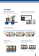
Controller Control system overview User's needs are supported by offering a variety of controls, such as individual control, central control and building management control options.
Air Conditioning Centralized Control System Controller Touch Panel Controller Software UTY-APGX N E W UTY-ALGX (Lite edition) UTY-DTGG USB Adaptor *2 (Field supplied) Internet or Public Telephone Line Central Remote Controller UTY-DCGG Remote/Monitoring side Group Remote Controller UTY-CGGG Convertor / Adaptor (for external device) Network Convertor UTY-VGGXZ1 BACnet® Gateway UTY-ABGX Software USB Adaptor *2 BMS/BAS *1 (Field supplied) Network Convertor (BMS/LONWORKS®) UTY-VLGX KNX® Interfac
Controller Comparison table of Controllers Item Wired Remote Controller (Touch panel) Wired Remote Controller Simple Remote Controller Simple Remote Controller*1 Wireless Remote Controller Group Remote Controller Central Remote Controller Touch Panel Controller System Controller Lite System Controller Software Software UTY-RNRG UTY-RLRG UTY-RSKG UTY-RHKG UTY-LNHG UTY-CGGG UTY-DCGG UTY-DTGG UTY-ALGX UTY-APGX Model name Max.
Max. controllable 16 Wired Remote Controller (Touch Panel ) : UTY-RNRG Indoor units Easy operation by high-definition large STN-LCD touch panel screen • Easy finger touch operation with LCD panel • Built-in weekly/Daily timer(ON/OFF,Temp.
Controller Max. controllable NEW 16 Wired Remote Controller : UTY-RLRG Indoor units • Various timer setup (ON / OFF / WEEKLY) are possible. • The room temperature can be controlled by detecting the temperature accurately with Built-in thermo sensor. • When a failure occurs, the error code is displayed. • Error history. (Last 16 error codes can be accessed.
Max. controllable 16 Simple Remote Controller : UTY-RSKG / UTY-RHKG (Without operation mode) Indoor units Compact remote controller provides access to basic functions • Up to 16 indoor units can be controlled with one remote controller. • Suitable for hotels or offices as it is easily operated with no complex functions.
Controller Max. controllable 16 Wireless Remote Controller : UTY-LNHG Indoor units Selectable 4 daily timers Simple and sophisticated operations with a choice of 4 daily timers •A single controller controls up to 16 indoor units. Built-in timers System addressing Select from 4 different timer programs: On / Off / Program / Sleep Program timer: The program timer operates the ON and OFF timer once within a 24 hour period.
Max.controllable 64 group R.C. in a VRF network system Group Remote Controller : UTY-CGGG Max. controllable 8 Group control of indoor units with simple operation remote controller groups •Up to 8 remote controller groups can be controlled by one Group Remote Controller. •Up to 64 Group Remote Controllers can be connected in one VRF network system. •Network Convertor is required to connect Group Remote Controllers to a VRF network system.
Controller Max. controllable 100 Central Remote Controller : UTY-DCGG Indoor units Central Remote Controller fits small- and medium-sized buildings and tenants. Max. controllable 16 • Individual control and monitor of 100 indoor units • 5 inch TFT color screen • High visibility and easy operation • External input / output contact • Detachable power supply unit • Corresponds to 7 different languages like English, Chinese, French, German, Spanish, Russian, Polish.
Max. controllable 400 Touch Panel Controller : UTY-DTGG Indoor units •Large-sized 7.5-inch TFT color •LCD Easy finger touch operation •Stylish shape and design to suit all application •No additional component is required for installation •Up to 400 indoor units can be controlled •Selectable 2 display types (Icon / List) in monitoring mode •Corresponds to 7 different languages, English, Chinese, French, German, Spanish, Russian, Polish.
Controller Max. controllable System Controller : UTY-APGX 4 Software VRF network systems Max. controllable 400 System Controller realizes the advanced integrated monitoring & control of VRF network system from small scale buildings to large scale buildings. outdoor units Max. controllable • Up to a maximum of 4 VRF network systems, 1600 indoor units, and 400 outdoor units can be controlled.
Diverse operation management & Data management Standard for System Controller and System Controller Lite Schedule management Error display & E-mail notification • Annual schedules can be set for each remote controller group / user defined group. Error is notified with popup message, audible sound and E-mail real time when error occurs. Error for the past 1 year are logged and can be reviewed later.
Controller Remote management Standard for System Controller Option for System Controller Lite UTY-PLGXR1 System Controller may be used on site or remotely over various networks for remote central control. System Controller requires 2 softwares working together. VRF Controller runs on site and communicate with VRF system. VRF Explorer runs remotely and provides user interface and communicate with the VRF Controller.
FUNCTIONS SUMMARY System controller Function System specification Site supervision Error management History Operation control Schedule Remote managemment Electricity charge apportionment Energy saving management Others ż: Available. Type UTY-APGX Max. VRF networks supported Max. indoor unit / remote controller groups per VRF network Max. outdoor units per System controller Max. indoor units / remote controller groups per System controller Max.
Adaptor & Convertor Max. controllable BACnet® Gateway : UTY-ABGX 4 Software VRF network systems Max. controllable • It is possible to connect medium to large sized BMS to VRF network system via BACnet ®, a global standard for open networks. • A maximum of 1600 indoor units with 4 VRF network systems (a maximum of 400 indoor units & 100 outdoor units for one network system) can be connected to one BACnet ® Gateway. • It is possible to control or monitor VRF network system from BMS via BACnet ® Gateway.
Max. controllable Network Convertor for 4 : UTY-VLGX units to BMS Max. controllable 128 indoor units •For connection between VRF network system and a open network for management of small to medium-sized BMS and VRF network system. •The UTY-VLGX permits central monitoring and control of a VRF network system from a BMS through a interface. •Up to 128 Indoor units can be connected to one Network Convertor for Installation example Max. 100 outdoor units Max. 128 indoor units RB Unit Max.
Adaptor & Convertor KNX® Interface : FJ-RC-KNX-1i The KNX Interface allows a complete integration of air conditioners with KNX Network systems. •Simple installation due to small and compact size. •No separate external power supply required (just KNX bus power). •Can be used for single indoor units and group controlled (up to 16) indoor units. The KNX Interface can be used with or without Wired Remote Controller.
NEW Wireless LAN Interface : FJ-RC-WIFI-1 • It is the most advanced solution to remotely manage an Air Conditioning system using all sort of mobile devices such as Smartphones, Tablets and PC • No separate external power supply required • Can be used for single indoor units and group controlled (up to 16) indoor units Indoor unit Internet Smartphone Smar Wireless LAN Interface Tablet Router (Field supplied) PC Basic control • Turning the units on and off • Mode control (Heat, Cool, Dry, Auto, Fan)
Adaptor & Convertor External Switch Controller : UTY-TEKX Air conditioner switching can be controlled by connecting other sensor switches •In combination with a field supply Card-Key Switch or other sensor, the External Switch Controller allows control of the ON / OFF, Room temperature, Fan speed and Master control functions. This makes this product suitable for installations such as hotel rooms. •Card-key or other sensor switches are available as a field supplied parts. Electrical wiring Room temp.
Max. controllable 16 Network Convertor : UTY-VGGXZ1 Network Convertor units •This network convertor is to be used for connecting single split system or group remote controller with the VRF network system. •Please select the function by switching the dip switch during the installation. Installation example •Split type systems can be controlled from a central remote controller or PC controller through connection to the VRF's network convertor.
Service & Maintenance Max. Monitor and controll Service Tool : UTY-ASGX 400 Software indoor units Max. Monitor and controll Extensive monitoring and analysis functions for installation and maintenance 100 outdoor units •Operation status can be checked and analyzed to detect even the smallest abnormalities •Storage of data on system operation status on a PC allows access even from off site.
VRF network system can be supported Web Monitoring Tool : UTY-AMGX 4 Software Product features •Troubleshooting is performed by monitoring each air conditioning unit remotely during periodical system checks. •Error notification can be automatically transmitted to several locations using the internet*1. •Requires either a dedicated internet connection or public telephone line.
OPTIONAL PARTS for VRF Connection Units Separation Tube Gas Pipe Gas Pipe Gas Pipe Gas Pipe Liquid Pipe Liquid Pipe Liquid Pipe Liquid Pipe UTP-AX054A UTP-AX090A UTP-AX567A UTP-AX180A Suction Gas Pipe Suction Gas Pipe Suction Gas Pipe Discharge Gas Pipe Discharge Gas Pipe Discharge Gas Pipe Liquid Pipe Liquid Pipe Liquid Pipe UTP-BX090A UTP-BX180A Header UTP-BX567A Outdoor Unit Branch Kit Gas Pipe Gas Pipe Gas Pipe Liquid Pipe Liquid Pipe UTR-H0906L / UTR-H1806L Liquid d Pipe
Specifications Separation Tube Model name Total cooling capacity of indoor unit (kW) Model name Total cooling capacity of indoor unit (kW) UTP-AX054A (for J-IIS only) UTP-AX090A UTP-AX180A UTP-AX567A 19.6 or less 28.0 or less 28.1 to 56.0 56.1 or more UTP-BX090A UTP-BX180A UTP-BX567A 28.0 or less 28.1 to 56.0 56.1 or more Header 3 í 6 Branches UTR-H0906L UTR-H1806L 3 í 8 Branches UTR-H0908L UTR-H1808L 28.0 or less 28.1 to 56.
OPTIONAL PARTS for VRF Controllers For Individual Control Wired Remote Controller (Touch Panel ) Wired Remote Controller N E W UTY-RLRG Simple Remote Controller UTY-RSKG With operation mode UTY-RNRG Simple Remote Controller UTY-RHKG Wireless Remote Controller UTY-LNHG Without operation mode IR Receiver Unit UTB-YWC For All Duct type IR Receiver Unit UTY-LRHGB1 For Cassette type For Centralized Control Group Remote Controller UTY-CGGG System Controller Lite N E W UTY-ALGX 172 Central Remote Cont
Convertors / Adaptors For External device BACnet ® Gateway UTY-ABGX Network Convertor Software for LONWORKS® KNX® Interface FJ-RC-KNX-1i UTY-VLGX DVD-ROM (Software) MODBUS® Interface FJ-RC-MBS-1 Software Protection Key Wireless LAN Interface N E W FJ-RC-WIFI-1 External Switch Controller UTY-TEKX For System expansion Network Convertor UTY-VGGXZ1 Signal Amplifier UTY-VSGXZ1 Panels For Cassette type Cassette Grille UTG-UFGC-W Cassette Grille UTG-UGGA-W For Compact Cassette type For Cassette typ
OPTIONAL PARTS for VRF Others Communication system: External Connect Kit For Indoor unit For Outdoor unit UTY-XWZXZ7 UTY-XWZXZD UTY-XWZXZ6 UTY-XWZXZB UTY-XWZXZ9 UTY-XWZXZE UTY-XWZXZC For RB unit For Central Remote Controller For Touch Panel Controller UTY-XWZXZ6 UTY-XWZXZ7 UTY-XWZXZA UTY-XWZXZ8 UTY-XWZXZB UTY-XWZXZA Function list Controller Indoor unit Operation / Stop All On / All Off – Batch Stop – UTY-XWZXZD UTY-XWZXZB Emergency Stop UTY-XWZXZD UTY-XWZXZB Forced Thermostat off UT
For Duct type Flange (Round) UTD-RF204 Flange (Square) UTD-SF045T Remote Sensor Unit UTY-XSZX For Medium Static Pressure Duct type / Ceiling type For Medium Static Pressure Duct type For All Duct type New amenity space can be offered by installing the Remote sensor.
FEATURE Title EXPLANATION Comfortable Function Convenient Function Human sensor Sleep timer Human sensor catches movements of people in a room. The micro-computer gradually changes the room temperature automatically to afford a comfortable night's sleep. Up / down swing flaps The up / down flaps automatically swing up and down. Program timer This digital timer allows selection of one of four options: ON, OFF, ON OFF or OFF ON.
Feature Summary Compact Cassette / Cassette Floor/Ceiling Wall Mounted Slim Duct Medium Static Pressure Duct High Static Pressure Duct Ceiling Floor AR AU AB HG HG HG 24 30 30 /3 /3 HG /3 AB 12 6/ 6 6 LR 45 LR 18 /1 H 4/ LM G /3 L T AS AS E, 1 E 1 0 8 LA 8 , L HG HG AG AS AU AR LV LV AB AS AR FC ,A LB TB 07 HG 07 HG HG HG HG HG AS AR A, HG RH /0 , /0 , A 0 HG 09 HC 36 45 AU 36 07 AB 12 9/ 9/ G 7 S /0 /1 /4 12 HG /5 /4 /0 30 12 /1 72 HG 09 H 9 2 5 4 5 9 4/ G2 /1 /3 /1 /1 /1 /5 /6 /9 /1 /5 /1 24 24 18 4L