
Specifications


Alignment & Adjustments 44 17730-248
AIRTEK
®
•
SOFTEK
®
for Blue Bird Buses
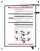
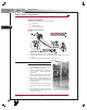
9. The different referenced ride height measurements are as specified in the following
chart. If the reference measurement is not within ± ¼" of the specification, the ride
height MUST be adjusted.
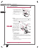
10. Detach the upper grommet of the height control valve linkage from the stud on the lev-
eling valve arm and exhaust suspension system air, see Figures 8-14 and 8-15.
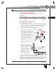
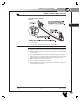
11. Adjust the height control valve by loosening the ¼" mounting locknuts and pivoting the
valve body about the mounting bolt.
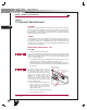
NOTE It is necessary to place a
3
⁄16" Allen wrench in the head of the mounting bolts while
adjusting ride height to prevent movement of the bolts, which can cause air leakage in the
body of the leveling valve.
12. Facing the air spring from the outboard side of the vehicle, pivot the valve body clock-
wise to increase the ride height and counter clockwise to decrease the ride height.
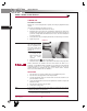
13. Tighten the ¼" mounting locknuts to 8-10 foot pounds, (see Figures 8-14 and
8-15) and repeat steps 4 through 10 until the reference measurement equals ± ¼" of
the specification, see Figures 8-12 and 8-13.
14. Remove wheel chocks.
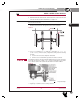
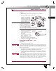
FIGURE 8-14 FIGURE 8-15
AIRTEK (FRONT) COMFORT AIR (REAR)
RIDE HEIGHT
SHOCK ABSORBER
LENGTH
RIDE HEIGHT
SHOCK ABSORBER
LENGTH
Dimension A Dimension B
Blue Bird Model
From the bottom of the
frame to the center of axle
At ride height with a
tolerance of ¼"
From the bottom of the
frame to the bottom of the
main support member.
At ride height with a
tolerance of ¼"
Vision 10K 12½" 18
9
⁄16"
4
7
⁄8" 22¾"All American Front Engine 14
7
⁄8" 17¼"
All American Rear Engine 14
7
⁄8" 17
15
⁄32"
L
86
1
APPENDIX
SERVICE MANUAL