
Specifications

Component Replacement 52 17730-248
AIRTEK
®
•
SOFTEK
®
for Blue Bird Buses
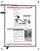
FIGURE 9-4 14.6K
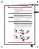
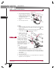
4. Remove the air lines from the height con-
trol valve, see Figure 9-4. The air lines
are push-to-connect. Push in on the air
line to release tension, push down on the
collar and pull out the air line.
5. Remove the two ¼" mounting nuts and
washers.
6. Remove the height control valve.
ASSEMBLY
1. Re-install the air fittings into the height control valve. Ensure the Teflon
®
thread seal-
ing ring is seated around the base of the fitting’s hex shoulder. Torque to 3-15 foot
pounds (4-20 Nm).
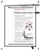
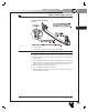
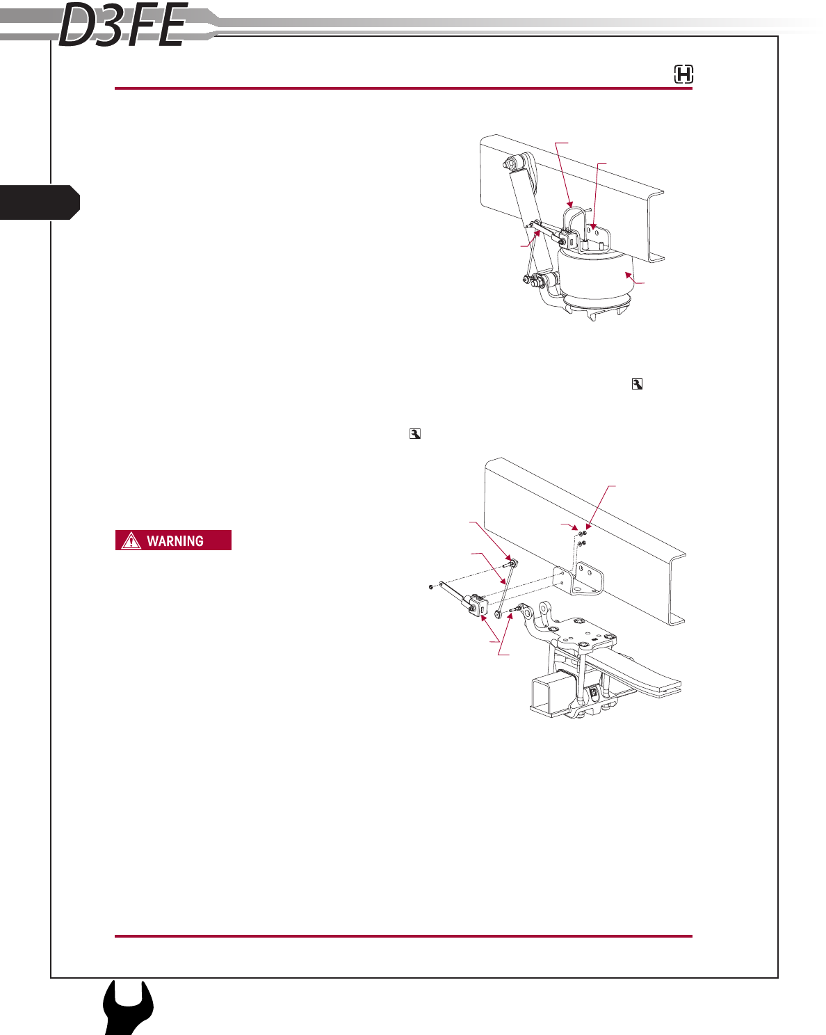
2. Install the height control valve to the upper air spring bracket by attaching the ¼" wash-
ers and locknuts. Torque to 8-10 foot pounds, see Figure 9-5.
FIGURE 9-5 14.6K
3. Install the air lines to the
height control valve. Refer
the Plumbing Diagram
Section of this publication.
PRIOR TO AND DURING
DEFLATION AND INFLATION OF
THE FRONT AIR SUSPENSION
SYSTEM, ENSURE THAT ALL
PERSONNEL AND EQUIPMENT
ARE CLEAR FROM UNDER THE
VEHICLE AND AROUND THE
SERVICE AREA, FAILURE TO DO SO
CAN CAUSE SERIOUS PERSONAL
INJURY, DEATH, OR PROPERTY
DAMAGE.
4. See additional Air Spring
Cautions and Warnings in
the Important Safety otice
Section of this publication prior to inflating or deflating the suspension system.
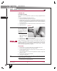
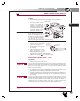
5. Inflate the suspension by connecting the height control valve linkage to the height con-
trol valve arm and lower mounting bracket. Verify the air springs inflate uniformly
without binding.
6. Remove the frame supports.
7. Remove the wheel chocks.
8. Verify proper ride height adjustment, (see ride height adjustment in the Alignment &
Adjustments Section of this publication).
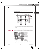
Height Control
Valve
Linkage
Assembly
Rubber
Grommet
Link
Mount
¼ Locknuts
Tightening Torque
8-10 ft. lbs.
"
¼ Washers"
¼ Nylon Air Line"
Leveling
Valve Arm
Air Spring Bracket
Air Spring
L
94
1
APPENDIX
SERVICE MANUAL