2.
Contents Guarantee/Warranty.............................................. 2 Warning.................................................................... 2 Vital Safety Info....................................................... 2 WEEE Disposal........................................................ 2 Important Notice..................................................... 1 Warning.................................................................... 1 Connector Connection........................................
Important Notice This manual is supplied with Escale 5-channel and EScale 6-channel transmitters. Please note that the 6th channel and trainer switch mentioned in this manual are not functional on the EScale 5-channel transmitter. Warning Connector Connection Insert the receiver, servo, and battery connectors fully and firmly. If vibration, etc. causes a connector to work loose during flight, the plane may crash.
Transmitter Layout Antenna Power Down Mode (PDM) Button Trainer Switch Ch.6 Switch Ch.
Adjusting the Servo Reverse Switches Before making any adjustments, set all the SERVO REVERSER switches on the front of the transmitter to the lower Perpendicular Rod (NOR) position. (Switch the switches with a small screwdriver, etc.) Turn on the transmitter and receiver power switches and make the following adjustments: 1. Check the direction of operation of each servo. If a servo operates in the wrong direction, switch its SERVO REVERSER switch.
Escale 2.4GHz FHSS Radio System Setup 2.4GHz radio systems have different characteristics than that of the conventional frequencies therefore please read this section carefully to enjoy safe flight with the 2.4GHz system. Receiver Antenna Installation The Escale receiver has two antennas. Position the antennas as shown below to ensure a strong signal for maximum range. 1. The two antennas must be kept as straight as possible. Otherwise it will reduce the effective range. 2.
Transmitter Antenna 1. The transmitter antenna is adjustable so please make sure that the antenna is never pointed directly at the model when flying as this creates a weak signal for the receiver. 2. Keep the antenna perpendicular to the transmitter’s face to create a better RF condition for the receiver. Of course this depends on how you hold the transmitter, but in most cases, adjusting the transmitter antenna so that it is perpendicular to the face will give the best results.
Range Check the Radio A range check must be performed before the first flight of a new model. It is not necessary to do a range check before every flight (but is not a bad idea to perform a range check before the first flight of each day). A range check is the final opportunity to reveal any radio malfunctions, and to be certain the system has adequate operational range. 1. There is “Power Down Mode” built in for doing a ground range check.
Transmitter Controls Before making any adjustments, learn the operation of the transmitter and the movement of each servo. (In the following descriptions, the transmitter is assumed to be in the standby state.) Aileron Operation When the aileron stick is moved to the right, the right aileron is raised and the left aileron is lowered, relative to the direction of flight, and the plane turns to the right. When the aileron stick is moved to the left, the ailerons move in the opposite direction.
Receiver Connection Example Connection example is shown below. 4G H z 1 2..
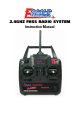
2.4GHz FHSS Radio System Australasia agents: Model Engines, Melbourne, Australia www.modelengines.com.au European agents: J Perkins Distribution, Lenham, England www.jperkinsdistribution.co.uk 07.