
User Guide


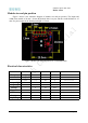
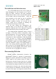
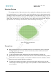
Table Of Contents

5.8Ghz low power radar sensor
Radar sensor
Version 1.0
Page 6
The hold time and detection area
The AT58L4MD-2020 pin has an IIC signal pin.
When debugging, the host computer can be used to
adjust the delay, sensitivity and other parameters
through the IIC; there is also a reserved MCU position
on the module, and the sensing distance , Delay and
other parameters of the radar can also be initialized
through the MCU on the module.in addition, 3
sensitivity condition resistors are reserved on the
module, which can be adjusted by adjusting the
resistance shown in Figure 3 on the right.
In the state without any configuration, the
induction delay is 15S, and the OUT output is high
during the induction time. If the induction is triggered
again within the delay time, the timing will restart.
The sensing distance adjustment resistor is shown
in Figure 4. The three resistors correspond to three
threshold parameters. The resistor positions are th0, th1
and th2 from top to bottom. The three resistors
correspond to 8 logic combinations. When there is no
resistor, the logic is 1. Figure 4 lists the thresholds
corresponding to various combinational logics. When
the threshold is smaller, the sensing distance is farther,
when the threshold is larger, the sensing distance is
closer. The sensing distance is the farthest when the
three resistors are not attached. When the resistors are
all pasted, the sensing distance is the shortest, and the
intermediate state can be deduced by analogy。
Photosensitive Detection
Module supports photosensitive detection, but
photosensitive function is optional. If photosensitive
function is required, photodiode and tuning resistance
can be added at the position shown in Figure 4.
Photosensitive detection function shall also be enabled
synchronously in software, and photosensitive threshold
can be adjusted by tuning resistance.Turn on the version
of photosensitive function, only when the ambient light
is lower than the set illuminance, the radar sensing will
be started. If the light is too bright, the module will not
Figure 3 sensitivity
condition resistors
sensitivity
Figure 4 sensing threshold
Figure 5 photodiode and
tuning resistance