
Specifications


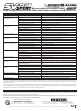

TR
2
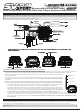
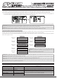
Making Receiver Connections and Mounting the Super Vortex-Plus Sport ESC:
1) Plug your steering servo into the ST channel port, making sure to observe correct polarity. If you’re using a gyro, such as the Sanwa SGS-01C,
plug the gyro into the AUX2 channel port. Make sure to observe correct polarity - Blue (Signal), Red (Positive) and Black (Negative).
2) Using two suitable sizes of double-sided foam tape (not included), mount the ESC and the ESC On/Off switch to
your model’s chassis.
3) Securely plug one end of the sensor cable into the Sensor Input port on the ESC, then securely plug the other
end of the sensor cable into the Sensor Input port on your motor. The sensor cable must be installed for proper
operation.
4) Slide the antenna wire into an antenna tube (not included) and secure the antenna tube in a vertical position. For
the best reception, the antenna wire should be mounted vertical and extend outside the top of your model.
• For maximum efficiency, orientate the ESC so that the cooling fins are parallel to the airflow. Do not wrap the
ESC in foam rubber, mount the ESC in a receiver box, or in any way block airflow to the cooling fins.
• Install the On/Off switch on the chassis of your model in a location that’s convenient to access and that doesn’t
interfere with any moving parts. In addition, it may be necessary to secure the battery and/or motor wires to
your chassis to prevent damage to them. Secure the capacitor to the ESC battery wires or the chassis using
a nylon cable tie (not included) to prevent it from being damaged or from shaking loose during use.
• In some cases, such as when there is limited airflow over the ESC or if your using a higher than normal Timing Advance value, a
cooling fan (not included) can be used help prevent the ESC from going into thermal shutdown. A 25 x 25 x 10mm cooling fan with
M2.6 x 13mm mounting screws can be used. The cooling fan should be orientated so that the direction of airflow blows air onto
the cooling fins.
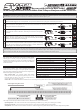
Antenna Tube
Coaxial Cable
Antenna
Reception Wire
The binding procedure allows you to bind the transmitter and receiver pair. Once the binding procedure is complete, the setting is remembered
even when the transmitter and receiver are turned OFF. The bind code is unique to each transmitter and receiver pair, so you don't need to worry
about other users' transmitters interfering with your receiver. You are only able to bind one transmitter to the receiver at any one time.
IMPORTANT: A motor cooling fan, lap counter device, LED light set, etc., in addition to a gyro or a servo, can be plugged into the AUX2 channel
port using a standard Y-harness (not included). In the default configuration, the AUX2 channel is controlled by your transmitter’s Auxiliary Lever.
If desired, this can be changed in the transmitter’s KEY ASSIGN menu.
IMPORTANT: Before beginning the binding procedure, make all battery and ESC/receiver connections as described in the previous section.
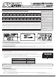
G
R
B
Green
Red Blue