
Specifications


TR
3
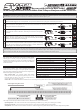
Bind LED Condition Indicator:
The Bind LED can be used to determine receiver condition at a glance. The Bind LED will alert you to various receiver conditions, as described below:
Bind LED
Blue
Blue Flash Slow/Blue Flash Fast
Red & Blue Flashing
Red
Condition
Receiving RF Signal
Binding Operation
Receiver Battery Fail Safe Activates
No RF Signal After Receiver Battery Fail Safe Activates
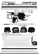
3) While holding down the Bind Button on the receiver (use a non-metallic instrument,
such as a toothpick), turn the ESC ON. The Bind LED on the receiver will flash
slowly. Release the Bind Button. The Bind LED on the receiver will continue to
flash slowly.
4) From within the transmitter's BIND menu, scroll to highlight the BIND [ENTER] field, then press the ENTER
key on your transmitter (within ~ 5 seconds of releasing the Bind Button). The [ENTER] command will begin
to flash and the Bind LED on the receiver will flash rapidly, then go out.
5) After the Bind LED on the receiver goes out, press the ENTER key a second time. The Bind LED on the
receiver will illuminate solid blue, indicating that the binding procedure is complete. Press and HOLD the
Back/Cancel key to exit the BIND menu.
IMPORTANT: The BIND menu may vary depending on your transmitter model. If necessary, refer to your transmitter's User's Guide for more
information about the binding procedure. When the binding procedure is successful, the Bind LED on the receiver will illuminate solid blue. If
the Bind LED on the receiver is flashing rapidly or is not illuminated at all, the transmitter and receiver are not paired. In this case, turn both the
transmitter and the ESC OFF, then repeat the binding procedure again.
1) Turn the transmitter ON and navigate to the BIND menu, then choose your transmitter's modulation type. If using an M12, MT-4S, EXZES-Z,
MT-4 or other FH4T transmitter, choose FH4T. If using an M11X, MX-3X or other FH3 transmitter, choose FH3.
2) Plug your motor battery into the ESC and verify that the ESC On/Off Switch is turned OFF (no lights on ESC).
(1) Press & HOLD
(2) Turn ON
The Servo Mode setting is used to change the
response time of the receiver to suit the type of
servos you're using. The combination of using
digital servos and using the correct Servo Mode
setting results in increased reaction speed and
improved feel, making you feel more connected to your model than ever. For example, using the SHR Servo Mode setting with any brand of digital
servo will increase the servo's response time, even above the manufacturer's specification. For the fastest response time possible, use the SSR
Servo Mode setting with Airtronics or Sanwa Super Response SRG digital servos.
For more information about the Servo Mode setting and how to program it, refer to your transmitter's User's Guide. The following Servo Modes can
be programmed from your transmitter's Modulation Menu:
NOR - Use with any brand of Analog or Digital servos.
SHR - Use with any brand of Digital servos only. Do not use with Analog servos!
SSR - Use with Airtronics or Sanwa SRG Digital servos only. Do not use with Analog servos or any other type or brand of Digital servos!
The Fail Safe function can automatically move the ESC throttle and servo(s) to a predetermined position in the event that the signal between the
transmitter and the receiver is interrupted, whether due to signal degradation or low transmitter battery. The Fail Safe function can be programmed
independently on all channels and three options are available: FREE, HOLD and PERCENTAGE. For information about programming the Fail Safe
function, refer to your transmitter's User's Guide.
WARNING: If you're using analog servos, DO NOT use SHR or SSR Servo Modes for that channel. Use the NOR Servo Mode with analog servos.
Using SHR or SSR Servo Modes with analog servos can result in damage to the servos or the receiver!
The Super Vortex-Plus Sport ESC is compatible with all Servo Modes.
The SSR Servo Mode is available only when using FH4T modulation. In addition, Servo Mode options may differ depending on the transmitter
model used. When switching between SHR and SSR Servo Modes, your model's End Point Adjustment (EPA) settings may be altered. In this
case, you should double-check the EPA settings and readjust them if necessary.
IMPORTANT: The Fail Safe function will NOT OPERATE if the receiver loses power. It will operate only if the transmitter and receiver signal is
interrupted or if the transmitter loses power. A Receiver Battery Voltage Fail Safe function is also featured.
After binding your transmitter to the receiver, follow the steps in this section to
setup your transmitter and calibrate the throttle end points.
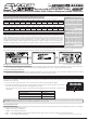
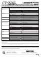
1) Adjust your transmitter’s throttle channel D/R, EPA, EXP, ARC, Sub-Trim,
Trim Switch and Servo Reversing settings to the values shown in the table
at right. Refer to your transmitter’s User’s Guide for information about
changing these settings. Not all transmitters may support all options.
Throttle Channel High Side and Brake Side D/R
Throttle Channel High Side and Brake Side EPA
Throttle Channel High Side and Brake Side EXP
Throttle Channel High Side and Brake Side ARC
Throttle Channel Sub-Trim
Throttle Trim Switch
Throttle Channel Servo Reversing*
100%
100%
OFF or 0%
OFF or 0%
0 or Centered
Centered
NOR or REV
*Do Not Change After Calibration.
B