Page 1
TaBLE OF cOnTEnTS Introduction......................................................................................................................................................................... Page 3 Additional Receiver Information ................................................................................................................................. Page 3 Transmitter Signal Range ...............................................................................................................
We appreciate your purchase of the Airtronics SD-6G 2.4GHz FHSS-1 radio control system. This Operating Manual is intended to acquaint you with the many unique features of your new radio control system. In designing the SD-6G 2.
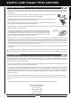
SaFETy anD USagE PREcaUTiOnS gEnERaL SaFETy l Be certain to read this Operating Manual in its entirety. l 'Safety First' for yourself, for others, and for your equipment. l l l Observe all the rules of the flying site or anywhere you operate your radio control equipment. l l l If at any time during the operation of your model should you feel or observe erratic operation or abnormality, end your operation as quickly and safely as possible.
SaFETy anD USagE PREcaUTiOnS l l l l l l l l The receiver antenna wires consist of two coaxial cables and two reception wires (the thin tip at the end of the coaxial cables). When you mount the receiver antenna wires, do not bend the reception wires. Reception performance decreases if the reception wires are bent. The receiver antenna wires are delicate, therefore, handle with care. Do not pull on the receiver antenna wires with force. Do not cut or extend the receiver antenna wires.
FEaTURES anD SPEciFicaTiOnS gEnERaL SySTEM FEaTURES l 6-Channel 2.4GHz FHSS-1 Digital Proportional Computer Radio Control System for Aircraft and Helicopters l Full-Range 92224 (RX600) 6-Channel 2.
FEaTURES FaMiLiaRizaTiOn Use the diagrams below to familiarize yourself with the basic features of your SD-6G 2.4GHz FHSS-1 transmitter. Descriptions of these features can be found on pages 8 and 9. The transmitter antenna is adjustable. It should be adjusted so that when you're holding the transmitter while you're flying, the antenna is orientated as close to perpendicular to the ground as possible at all times. This provides the best signal between the transmitter and the receiver.
FEaTURES FaMiLiaRizaTiOn REcEivER FEaTURES DiagRaM Use the diagram below to familiarize yourself with the 92224 (RX600) 6-Channel receiver included with your SD-6G 2.4GHz FHSS-1 radio control system. Descriptions of these features can be found below and on the next page.
FEaTURES FaMiLiaRizaTiOn Multi-Function LCD: The heart of the programming and display features of the transmitter. All programming and transmitter display functions are shown on the Multi-Function LCD. Navigation Pad: The Navigation Pad is used in conjunction with the Programming Keys to facilitate transmitter programming. The Navigation Pad allows you to quickly and easily move the Programming Cursor up and down, and right and left.
FEaTURES FaMiLiaRizaTiOn TRanSMiTTER aLaRMS, cOnTinUED.... Trainer Mode Warning Alarm The SD-6G transmitter is equipped with a safety feature that will warn you when the transmitter is set to Trainer>Master or Trainer>Slave when the transmitter is turned ON.
FEaTURES FaMiLiaRizaTiOn The information in this section describes the basic steps that you can use to quickly setup a new model. Regardless of the model you are flying, using the basic functions of the SD-6G transmitter for most applications is easy and will get your model setup quickly. It's a simple five-step process. The information in this section is general in nature.
FEaTURES FaMiLiaRizaTiOn TiPS anD SUggESTiOnS, cOnTinUED.... l l l l l l l l l l l l l l l l l l l An after-market peak-detection charger, cycler, or fast charger should NOT be used to charge Ni-Cd or Ni-MH rechargeable batteries through the transmitter. The circuitry within the transmitter can interfere with the peak-detection charger's normal operation, resulting in over-charging and damaging the batteries, and possibly the transmitter itself.
SySTEM cOnnEcTiOnS 1) Remove the battery cover on the back of the transmitter by pushing down firmly on the tab in the top of the battery cover and pulling the battery cover out. 2) Install six 'AA' batteries into the battery tray, making sure that the polarity is correct. The direction that each battery should be installed is molded into the battery tray (+ Positive and - Negative). 3) Set the bottom of the battery cover back onto the transmitter and push it firmly until it 'clicks' closed.
SySTEM cOnnEcTiOnS TRanSMiTTER anD REcEivER BaTTERy chaRging The SD-6G transmitter features a Charging Jack, which can be used with the Airtronics 95034 110v AC Transmitter and Receiver Dual Charger to recharge the batteries without removing them from the transmitter. In addition, this charger can also be used to recharge a 4.8v (4 cell) or 6.0v (5 cell) rechargeable Ni-Cd or Ni-MH receiver battery pack at the same time. We recommend one of the following receiver battery packs: Hi-Energy 4.
The SD-6G transmitter features four Programming Keys, a Navigation Pad and an ENTER key, all used in conjunction to facilitate transmitter programming. This section summarizes the functions of these features in addition to detailing the main areas of the Multi-Function LCD. PROgRaMMing kEyS OvERviEw anD FUncTiOnS Moving around the LCD and programming the transmitter is accomplished using the Navigation Pad, the ENTER key, and the four Programming Keys positioned on the right half of the transmitter.
LcD anD PROgRaMMing kEyS MULTi-FUncTiOn LcD OvERviEw Use the diagram below to familiarize yourself with the layout and different indicators that make up the Multi-Function LCD. Model Number Timer Model Name Active Flight Mode Count Up Timer Indicator Trainer Status Indicator Throttle Trim Elevator Trim Voltage Indicator Model Type Icon Aileron Trim Rudder Trim Battery Capacity Indicator Active Flight Mode: Displays the Flight Mode number that is currently Active.
SySTEM SETUP anD inSTaLLaTiOn The Binding function allows you to Bind the transmitter and receiver pair. When new, it is necessary to pair the transmitter and receiver to prevent interference from transmitters operated by other users. This operation is referred to as 'binding'. Once the binding process is complete, the setting is remembered even when the transmitter and receiver are turned OFF. Therefore, this procedure usually only needs to be done once.
SySTEM SETUP anD inSTaLLaTiOn MOUnTing ThE REcEivER When mounting the receiver into your model, it's important to mount the receiver exactly as described. In addition, the receiver should be wrapped in foam rubber to protect it from vibration. Failure to mount the receiver antenna wires as described can result in poor reception, or in some cases, complete loss of reception.
SySTEM SETUP anD inSTaLLaTiOn The Low-Power Mode function lowers the transmitter's RF output level to check radio signal reception (Range Check). Use this function to check radio signal reception on the ground, prior to flight. IMPORTANT The radio control system should be Range Checked prior to the day's first flight and prior to the first flight after a hard landing or after a repair. This will ensure that the transmitter and receiver are communicating properly prior to flight.
FLighT MODES The SD-6G transmitter model programming is based around Flight Modes. Each Model Type (AERO and HELI) feature three independently programmable Flight Modes. Flight Mode FN (Normal), Flight Mode F1, and Flight Mode F2. Within these Flight Modes is where the core of the model programming takes place. Features such as Dual Rate, Exponential, Throttle Curve, Pitch Curve, Mixing, Compensation Mixing, and much more can be individually programmed to each of the three Flight Modes.
aERO MODEL TyPE cOnTEnTS General Information ......................................................................................................................................................... Page 22 AERO Model Type Menu Flow Chart .............................................................................................................................. Page 22 AERO Model Type Transmitter Layout .......................................................................................................
aERO MODEL TyPE gEnERaL inFORMaTiOn To access the AERO Model Type Programming Menus, turn the transmitter ON. From the Display screen, press the ENTER key to display the Programming Menus, then press the Navigation Pad 56to scroll to the desired Programming Menu. Press the ENTER key to access the desired Programming Menu. From within any Programming Menu, press the END/M3 key continuously to return to the Display screen. Unless otherwise noted, all programming changes take effect immediately.
aERO MODEL TyPE aERO MODEL TyPE TRanSMiTTER LayOUT The diagram below shows the transmitter control stick and switch layout in the AERO Model Type configuration.
aERO MODEL TyPE Selecting a Model, Continued.... 3) Press the Navigation Pad 56 to highlight the model you would like to select, then press the ENTER key to select the highlighted model. That model will be displayed above the Model Select List. When you press the ENTER key to select a model, the Programming Data for that model will be loaded immediately. In the default configuration, the Model Select List contains 5 AERO Model Types and 5 HELI Model Types.
aERO MODEL TyPE 02.MODEL naME (MODEL naMing), cOnTinUED.... Deleting a Character 1) Press the INC+/M1 or DEC-/M2 keys to move the underscore under the character you want to erase. 2) Press the Navigation Pad 5634 to highlight the Erase Bracket , then press the ENTER key to erase the underscored character. Deleting a Model Name 1) Press the INC+/M1 and DEC-/M2 keys at the same time to move the underscore under the first character. , then press the ENTER key repeatedly to erase the entire 03.
aERO MODEL TyPE Making AERO Model Type Selection Options, Continued.... 2) Press the Navigation Pad 56 to highlight the AERO Model Type selection option you wish to change, for example, AILE>1. 3) Press the INC+/M1 or DEC-/M2 keys to change the selection option. When a Model Type selection option is changed, ENTER will flash in the Programming Window. 4) Repeat steps 2 and 3 to change the options for any of the other AERO Model Type selection options you wish to change.
aERO MODEL TyPE 04.TRainER (TRainER SySTEM), cOnTinUED.... Activating the Trainer Function - Master (Instructor) Transmitter 1) Turn the Master (Instructor) transmitter ON. From the Display screen, press the ENTER key to display the Programming Menus. 3) Press the INC+/M1 key to change the current transmitter's Trainer mode to MASTER. >MASTER will be displayed. will be displayed on the Display screen, indicating that the transmitter is operating in MASTER mode.
aERO MODEL TyPE 05.STOP waTch (STOP waTch anD cOUnT UP TiMER) The Stop Watch function is used to either count down from a programmed Start time (Count Down mode) or to count up from zero if no Start time is programmed (Count Up mode). In Count Down mode, an audible tone will sound in 1 second intervals when the Stop Watch reaches 10 seconds from zero. When zero is reached, a long audible tone will sound and the Stop Watch will begin to count up.
aERO MODEL TyPE 06.DaTa cOPy (MODEL PROgRaMMing DaTa cOPy) The Data Copy function allows you to copy the Programming Data from one model to another model. This is convenient if you have similar Model Types. For example, if you have two models that are similar, you can copy the Programming Data from the first model to the second model to use as a base to start fine-tuning the programming for the second model.
aERO MODEL TyPE 07.DaTa RESET (MODEL PROgRaMMing DaTa RESET), cOnTinUED.... Although Model Type selection options are model-specific, the Data Reset function does NOT Reset them. This is useful if you have two similar models, but different programming needs for each. For example, if you have two similar aircraft that use the same Model Type selection options (e.g., TAIL>2xEL and AILE>2) but different Programming Data (e.g.
aERO MODEL TyPE Changing Servo Reversing Adjustment Values, Continued.... 3) Press the Navigation Pad 5634 to highlight the channel that you would like to change the Servo Reversing adjustment value for. 4) Press the INC+/M1 or DEC-/M2 keys to change the REV adjustment value to set the desired direction of servo travel. REVERSE setting range is NOR/REV. The default setting is NOR. 09.
aERO MODEL TyPE Changing Servo Centering Percentage Values, Continued.... 3) Press the Navigation Pad 5634 to highlight the channel that you would like to change the Servo Centering percentage value for. 4) Press the INC+/M1 or DEC-/M2 keys to change the Servo Centering percentage value to center the servo horn. 5) Repeat steps 3 and 4 to center the servo horns for the desired remaining channels. CENTER setting range is -150% to 150%. The default setting is 0%.
aERO MODEL TyPE Changing Servo End Point Percentage Values, Continued.... In front of each End Point Adjustment percentage value is a specific icon. To set the End Point Adjustment percentage value for the desired direction of servo travel, the control stick or switch must be moved in the direction of servo travel you want to change the End Point Adjustment percentage value for.
aERO MODEL TyPE Changing the Throttle Cut Percentage Value, Continued.... 3) Press the INC+/M1 or DEC-/M2 keys to set the position you would like the throttle servo to move to when you press the Throttle Cut button. TH-CUT setting range is -150% to 0%. The default setting is -100%. Decreasing the Throttle Cut percentage value will increase throttle servo travel when the Throttle Cut button is pressed. 12.
aERO MODEL TyPE 12.D/R & EXP (DUaL RaTE anD EXPOnEnTiaL), cOnTinUED.... Dual Rate Overview The Dual Rate function allows you to change the control authority of the control surfaces by changing the amount of servo travel.
aERO MODEL TyPE 12.D/R & EXP (DUaL RaTE anD EXPOnEnTiaL), cOnTinUED.... Choosing the Channel 1) Press the Navigation Pad 34 to highlight the channel you would like to make Exponential percentage value changes to. Choose either , , or . Exponential can be set for EL (Elevator), AI (Aileron), and RU (Rudder). Changing the Exponential Percentage Values The Exponential function is linked directly to the Dual Rate switch.
aERO MODEL TyPE Choosing the Trim Flight Mode Option, Continued.... 3) Press the INC+/M1 or DEC-/M2 keys to choose the desired Trim Flight Mode option, either COMMON, SEPARATE or SEPARATE TH-TRIM LOCK (F1). WARNING When the Trim Flight Mode option is set to Separate or SEPARATE TH-TRIM LOCK (F1), Digital Trim values are stored in the specific Flight Mode you're using when you change the trim using the trim switches.
aERO MODEL TyPE Choosing the Flight Mode - Common or Separate, Continued.... 3) Press the Navigation Pad 5 to move the cursor to F-MODE>COM. 4) Press the INC+/M1 or DEC-/M2 keys to choose either SEP OR COM (SEParate or COMmon). 5) If you choose SEPARATE, press the F-MODE key to choose the F-MODE number you would like to program the Throttle Curve function for. Choose from FN, F1 or F2.
aERO MODEL TyPE 15.ai-DiFF (aiLEROn DiFFEREnTiaL) The Aileron Differential function allows you change the ratio of the Up to Down movement of each aileron. For example, many aircraft exhibit a yaw tendency when the ailerons are used. Although this can affect any aircraft, it's noticed mostly on high-wing aircraft and aerobatic aircraft. The Aileron Differential function can be used to eliminate the yaw tendency by adding more movement to the upward moving aileron than the downward moving aileron.
aERO MODEL TyPE Changing the Aileron Differential Percentage Values, Continued.... 1) Press the Navigation Pad 56 to highlight the desired aileron travel direction you would like to change the Aileron Differential percentage value for. For example, if you need the Right Aileron to move Up more than the Left Aileron moves Down (per the previous diagram), you would decrease the LA-R>100% (Left Aileron-Right) percentage value.
aERO MODEL TyPE Choosing the Flight Mode - Common or Separate, Continued.... 3) Press the Navigation Pad 5 to move the cursor to F-MODE>COMMON. 4) Press the INC+/M1 or DEC-/M2 keys to choose either SEPARATE or COMMON. 5) If you choose SEPARATE, press the F-MODE key to choose the F-MODE number you would like to program the Flaperon Mixing function for. Choose from FN, F1 or F2.
aERO MODEL TyPE 17.FL4EL (FLaP TO ELEvaTOR MiXing), cOnTinUED.... Choosing the Flight Mode - Common or Separate 1) From the Display screen, press the ENTER key to display the Programming Menus. 2) Press the Navigation Pad 56 to highlight FL 4EL, then press the ENTER key to display the FL 4EL menu. The cursor will default to FL 4EL>0%. 3) Press the Navigation Pad 5 to move the cursor to F-MODE>COMMON. 4) Press the INC+/M1 or DEC-/M2 keys to choose either SEPARATE or COMMON.
aERO MODEL TyPE 18.DUaL EL (DUaL ELEvaTOR MiXing EnD POinT aDjUSTMEnT), cOnTinUED.... Transmitter F-MODE Transmitter F-MODE refers to the Flight Mode that the transmitter is currently operating in. Programming F-MODE refers to the Flight Mode that you would like to change the programming for.
aERO MODEL TyPE 19.aiLvaTOR (aiLvaTOR/TaiLEROn MiXing) The Ailvator Mixing function mixes ailerons and elevator, allowing you to have both roll control and pitch control on the elevator, separate from the ailerons. When Activated, not only will the two elevator halves move up and down together, but each elevator half can move up and down independently like ailerons. This function is commonly referred to as tailerons (or stabilators), and is normally found on aircraft that feature full-flying stabilizers.
aERO MODEL TyPE Changing Ailvator Mixing Percentage Values, Continued.... AILVATOR setting range is -100% to 100%. The default setting is 0% (OFF). Adjusting the Ailvator Mixing percentage values will change the ratio of elevator roll travel to elevator pitch travel. For example, when the Aileron4Left Elevator and the Aileron4Right Elevator percentage values are both set to 50%, the elevator roll travel will be half the amount of the elevator pitch travel at any given control stick position.
aERO MODEL TyPE 20.v-TaiL (v-TaiL MiXing EnD POinT aDjUSTMEnT), cOnTinUED.... Changing V-Tail Mixing End Point Adjustment Percentage Values - Rudder Right and Left 1) Press the Navigation Pad 6 to scroll down to display V-TAIL RU (L) and RU (R). 2) Press the Navigation Pad 5634 to highlight the desired servo (EL or RU) and direction of travel (L or R) you would like to change the V-Tail Mixing End Point Adjustment percentage value for.
aERO MODEL TyPE Changing Delta Mixing End Point Adjustment Percentage Values - Elevator Up and Down, Continued.... 3) Press the Navigation Pad 5634 to highlight the desired servo (EL or AI) and direction of travel (DOWN or UP) you would like to change the Delta Mixing End Point Adjustment percentage value for. For example, if the Elevator servo moves Up more than the Aileron servo moves Up when you move the elevator control stick, you would decrease the EL (UP) EL>80% percentage value.
aERO MODEL TyPE 22. & 23.c-MiX1 anD c-MiX2 (cOMPEnSaTiOn MiXing), cOnTinUED.... Transmitter F-MODE Programming F-MODE Transmitter F-MODE refers to the Flight Mode that the transmitter is currently operating in. Programming F-MODE refers to the Flight Mode that you would like to change the programming for. In all cases, the Master channel always controls the Slave channel. Choosing the Flight Mode - Common or Separate 1) From the Display screen, press the ENTER key to display the Programming Menus.
aERO MODEL TyPE 22. & 23.c-MiX1 anD c-MiX2 (cOMPEnSaTiOn MiXing), cOnTinUED.... Choosing the Slave Channel The Slave channel is the channel that is controlled by the Master channel. For example, if you set the Master channel to EL (Elevator) and the Slave channel to AI (Aileron), when you move the elevator control stick, the ailerons will move. SLAVE setting range is EL (Elevator), AI (Aileron), TH (Throttle), RU (Rudder), GE (Gear), and FL (Flap). The default setting is EL (Elevator).
aERO MODEL TyPE Changing the Offset Percentage Value The Offset percentage value changes the neutral position of the Slave channel servo when the Compensation Mixing function is Activated. For example, when an Offset percentage value is programmed, the Slave channel servo neutral position and its two End Point positions will 'shift' the programmed amount. 1) Press the Navigation Pad 6 to highlight OFFSET>0%. 2) Press the INC+/M1 or DEC-/M2 keys to change the Offset Percentage value.
hELi MODEL TyPE cOnTEnTS General Information ......................................................................................................................................................... Page 52 HELI Model Type Menu Flow Chart ................................................................................................................................. Page 52 HELI Model Type Transmitter Layout ...................................................................................................
hELi MODEL TyPE gEnERaL inFORMaTiOn To access the HELI Model Type Programming Menus, turn the transmitter ON. A helicopter icon will be shown on the Display screen. From the Display screen, press the ENTER key to display the Programming Menus, then press the Navigation Pad 56to scroll to the desired Programming Menu. Press the ENTER key to access the desired Programming Menu. If a helicopter icon is not shown on the Display screen, use the Model Select function to select a HELI model.
hELi MODEL TyPE hELi MODEL TyPE TRanSMiTTER LayOUT The diagram below shows the transmitter control stick and switch layout in the HELI Model Type configuration. IMPORTANT Since each of the three Flight Modes can be programmed separately, before making programming changes, verify that you are in the Flight Mode you want to make programming changes to.
hELi MODEL TyPE Selecting a Model, Continued.... 3) Press the Navigation Pad 56 to highlight the model you would like to select, then press the ENTER key to select the highlighted model. That model will be displayed above the Model Select List. When you press the ENTER key to select a model, the Programming Data for that model will be loaded immediately. In the default configuration, the Model Select List contains 5 AERO Model Types and 5 HELI Model Types.
hELi MODEL TyPE 02.MODEL naME (MODEL naMing), cOnTinUED.... Deleting a Character 1) Press the INC+/M1 or DEC-/M2 keys to move the underscore under the character you want to erase. 2) Press the Navigation Pad 5634 to highlight the Erase Bracket character. , then press the ENTER key to erase the underscored Deleting a Model Name 1) Press the INC+/M1 and DEC-/M2 keys at the same time to move the underscore under the first character. 2) Press the Navigation Pad 5634 to highlight the Erase Bracket Model Name.
hELi MODEL TyPE Making HELI Swashplate Type Selection Options, Continued.... 2) Press the Navigation Pad 6 to highlight SWASH>NORMAL. 3) Press the INC+/M1 or DEC-/M2 keys to change the Swashplate Type selection option. When a Swashplate Type selection option is changed, ENTER will flash in the Programming Window. The following Swashplate Type selection options are available. The diagrams display the swashplate geometry, the number of servos used, and the specific placement of those servos.
hELi MODEL TyPE 04.TRainER (TRainER SySTEM) The SD-6G transmitter features a Trainer System that allows you to connect two SD-6G transmitters to one another or connect one SD-6G transmitter to one SD-5G transmitter or to one SD-10G transmitter for the purpose of training a new pilot or for training a more experienced pilot on a new model. During use, one transmitter acts as the Master (Instructor) and the other transmitter acts as the Slave (Student).
hELi MODEL TyPE Activating the Trainer Function - Slave (Student) Transmitter, Continued.... 3) Press the INC+/M1 key to change the current transmitter's Trainer mode to SLAVE. >SLAVE will be displayed. will be displayed on the Display screen, indicating that the transmitter is operating in SLAVE mode. Using the Trainer Function 1) The Trainer Cable should be connected between the two transmitters and the Trainer function on both transmitters should be Activated as described previously.
hELi MODEL TyPE 05.STOP waTch (STOP waTch anD cOUnT UP TiMER), cOnTinUED.... Using the Stop Watch 1) Press the END/M3 key two times to return to the Display screen. The Start time that you programmed will be displayed. 2) To Start the Stop Watch, press the INC+/M1 key. To Stop the Stop Watch, press the DEC-/M2 key a second time. To Reset the Stop Watch to the programmed Start time, press the INC+/M1 and DEC-/M2 keys at the same time. The Stop Watch is displayed in Minutes, Seconds, and 1/10 Seconds.
hELi MODEL TyPE Copying Model Programming Data, Continued.... 4) Press the Navigation Pad 6 to move the cursor to the bottom model number, then press the INC+/M1 or DEC-/M2 keys to select the model you would like to copy Programming Data TO. ENTER will continue to flash in the Programming Window. It's not possible to copy Programming Data from one model to the same model. If you attempt this, ENTER will not flash. 5) Press the ENTER key.
hELi MODEL TyPE Resetting Model Programming Data, Continued.... 4) Press the ENTER key. DATA RESET OK? will be displayed and INC+ will flash. 5) Press the INC+/M1 key to Reset the Programming Data for the selected model. After ~10 seconds, the Programming Data will be Reset as indicated by the progress bar, and COMPLETE!! will be displayed in the Programming Window. Press any key to return to the DATA RESET menu.
hELi MODEL TyPE Centering the Trim Switches and Servo Horns, Continued.... 2) Install the servo horn onto the servo, making sure that the servo horn is as close to being centered as possible. In some cases you can get the servo arm closer to being centered by rotating the servo arm 180º and reinstalling it. IMPORTANT It is always recommended to install the servo horns as close to being centered as possible, prior to changing the Servo Centering percentage values.
hELi MODEL TyPE 10.EPa (EnD POinT aDjUSTMEnT) The End Point Adjustment function allows you to adjust servo travel in each direction. This makes it possible to balance control throw in both directions and set the maximum desired control throw. For example, if you want the elevator axis to move Up and Down 4 degrees in each direction, but the elevator axis moves Down more than 4 degrees, decrease the End Point Adjustment in the Down direction, so that the elevator axis moves Up and Down the same amount.
hELi MODEL TyPE 11.cP-EPa (ccPM EnD POinT aDjUSTMEnT) The CCPM End Point Adjustment function allows you to adjust servo travel in each direction for the elevator, aileron, and pitch servos independently. Unlike the standard End Point Adjustment function, which affects all the cyclic servos, CCPM End Point Adjustment allows you to adjust each cyclic servo independently without any affect on the other cyclic servos.
hELi MODEL TyPE 12.SwaSh (SwaShPLaTE SETUP), cOnTinUED.... IMPORTANT To be able to access the SWASH menu and program the Swashplate Setup function, you must choose a CCPM swashplate setup in the TYPE menu. The SWASH menu displays the default adjustment values for the Swashplate Type chosen in the TYPE menu. The currently selected Swashplate Type is displayed.
hELi MODEL TyPE 13.Th-cUT (ThROTTLE cUT), cOnTinUED.... There are several different methods that can be used to set up your throttle control linkage and the Throttle Cut function.
hELi MODEL TyPE Choosing the Flight Mode - Common or Separate, Continued.... 1) From the Display screen, press the ENTER key to display the Programming Menus. 2) Press the Navigation Pad 56 to highlight D/R & EXP, then press the ENTER key to display the D/R & EXP menu. The cursor will default to D/R>100%. 3) Press the Navigation Pad 5 to move the cursor to F-MODE>COMMON.
hELi MODEL TyPE Changing the Dual Rate Percentage Values, Continued.... 1) Move the Dual Rate switch to the position you would like to set a Dual Rate percentage value for, either 1 or 2. 2) Press the INC+/M1 or DEC-/M2 keys to set the desired Dual Rate percentage value for the channel you chose previously. D/R setting range is 0% to 150%. The default setting is 100%. Increasing the Dual Rate percentage value increases servo travel and decreasing the Dual Rate percentage value decreases servo travel.
hELi MODEL TyPE 15.TRiM (DigiTaL TRiM) The SD-6G transmitter features Digital Trim Memory. Any amount of control surface trim that you set during flight using the trim switches is automatically stored in memory for that specific channel and for that specific model. The Digital Trim values for each model will automatically be loaded when the transmitter is turned ON.
hELi MODEL TyPE 16.Th-cURvE (ThROTTLE cURvE), cOnTinUED.... Transmitter F-MODE Function Output 150% 100% Programming F-MODE Stick Input 0% 100% 150% Point Positions Transmitter F-MODE refers to the Flight Mode that the transmitter is currently operating in. Programming F-MODE refers to the Flight Mode that you would like to change the programming for.
hELi MODEL TyPE Changing the Throttle Curve Point Values and the Rate Percentage Values, Continued.... In the default configuration the Throttle Curve is Linear. For example, when you move the throttle control stick from 0% to 100%, the throttle servo will travel from 0% to 100%, too. As long as the line on the graph remains straight, the Throttle Curve will be Linear.
hELi MODEL TyPE Activating the Throttle Hold Function and Changing the Rate Percentage Value, Continued.... 1) Press the Navigation Pad 6 to highlight RATE>-100%. 2) Press the INC+/M1 or DEC-/M2 keys to set the position you would like the throttle servo to Hold at. HOLD setting range is -150% to 0%. The default setting is -100%.
hELi MODEL TyPE Choosing the Flight Mode - Common or Separate, Continued.... 3) Press the Navigation Pad 5 to move the cursor to F-MODE>COM. 4) Press the INC+/M1 or DEC-/M2 keys to choose either SEP OR COM (SEParate or COMmon). 5) If you choose SEPARATE, press the F-MODE key to choose the F-MODE number you would like to program the Pitch Curve function for. Choose from FN, F1 or F2.
hELi MODEL TyPE 18.REvO-MiX (REvOLUTiOn MiXing) The Revolution Mixing function mixes rudder and collective pitch controls, which makes the helicopter more stable when collective pitch is increased. For example, when you increase collective pitch, as the rotor head speed and pitch increase, the torque that it creates can cause the tail of the helicopter to pivot. Adding Revolution mixing helps prevent this from occurring, which makes the helicopter more stable in the yaw axis.
hELi MODEL TyPE Changing the Revolution Mixing Function High Side Percentage Value Changing the High side percentage value affects the Revolution Mixing function from half throttle stick to full throttle stick only. It has no effect on the Low throttle side. 1) Press the Navigation Pad 6 to highlight H>0%. 2) Press the INC+/M1 or DEC-/M2 keys to choose the desired High throttle side percentage value. REVO-MIX H setting range is -150% to 150%. The default value is 0% (OFF).
hELi MODEL TyPE 19.gyRO (REMOTE gyRO gain cOnTROL), cOnTinUED.... Choosing the Flight Mode - Common or Separate 1) From the Display screen, press the ENTER key to display the Programming Menus. 2) Press the Navigation Pad 56 to highlight GYRO, then press the ENTER key to display the GYRO menu. The cursor will default to 1>100%. 3) Press the Navigation Pad 5 to move the cursor to F-MODE>COMMON. 4) Press the INC+/M1 or DEC-/M2 keys to choose either SEPARATE or COMMON.
hELi MODEL TyPE Changing the Gyro Percentage Values, Continued.... GYRO 1 and GYRO 2 setting range is -150% to 150%. The default settings are 100%. Decreasing the GYRO percentage values decreases gyro gain and increasing the GYRO percentage values increases gyro gain. See the IMPORTANT note on the previous page regarding the use of positive and negative Gyro percentage values and how they may change your gyro operating mode.
hELi MODEL TyPE Choosing the Flight Mode - Common or Separate, Continued.... Two Compensation Mixing functions are available, however, only one Compensation Mixing function can be Active at one time. If F-MODE is set to COMMON, both Compensation Mixing functions will controlled by the Compensation Mixing switch and Compensation Mixer 2 will always override Compensation Mixer 1.
hELi MODEL TyPE Changing the Rate High and Rate Low Percentage Values, Continued.... 3) Press the Navigation Pad 6 to highlight RATE Lo>0%. 4) Press the INC+/M1 or DEC-/M2 keys to change the Rate Low Percentage value. RATE Hi and RATE Lo setting ranges are -150% to 150%. The default settings are 0%. Increasing or decreasing the Rate High and Rate Low percentage values will change the direction that the Slave channel servo travels and the amount that it travels relative to the Master channel servo.
hELi MODEL TyPE 22.SX MOniTOR (SERvO MOniTOR) The Servo Monitor displays the output levels of each of the 6 channels in bar graph form, allowing you to monitor servo operation in a virtual manner. This is helpful to see servo movement when the control sticks and switches are moved, and it allows you to visualize what is occurring with servo movements when you apply different mixing values.
REFEREncE TROUBLEShOOTing gUiDE This troubleshooting guide has been provided to help you diagnose and solve most problems that you may encounter with your SD-6G 2.4GHz FHSS-1 radio control system. Most problems encountered can be solved by following the problem-cause-solution sections. If you cannot solve the problem using this troubleshooting guide, please contact Airtronics Customer Service using the information on the back cover of this Operating Manual.
REFEREncE TROUBLEShOOTing gUiDE, cOnTinUED.... PROBLEM caUSE SOLUTiOn Cannot copy Programming Data Attempting to copy Programming Data to the same model number Copy Programming Data to a different model number LCD appears dark or hard to read Transmitter left in direct sunlight for too long Place transmitter in shade until LCD clears up.
REFEREncE gLOSSaRy OF TERMS, cOnTinUED.... Coaxial Cables: The portion of each receiver antenna wire that extends the Antenna Reception Wires. The Coaxial Cables can be bent into gentle curves, however, do not bend the Coaxial Cables acutely, or repeatedly bend them, or the antenna wire's cores can be damaged. Compensation Mixing: Allows you to mix two channels together, then apply that mixing to the channels themselves. Useful if you need to program a mix that is not already pre-programmed.
REFEREncE gLOSSaRy OF TERMS, cOnTinUED.... Model Name: The Model Name function allows you to name each of your individual models. This makes it easy to keep track of multiple models. The Model Name can consist of up to 8 letters, numbers, or symbols. Choose from capital letters, lower case letters, numbers, and various symbols. Model Select: The Model Select function allows you to load the programming for the particular model you wish to fly.
REFEREncE gLOSSaRy OF TERMS, cOnTinUED.... Temperature Range: The range in temperature of the outside air that the transmitter can safely and reliably operate in. Throttle/Rudder Control Stick: Controls the Throttle and Rudder axes. The Throttle/Rudder Control Stick length is adjustable to suit your preference. Throttle Cut: The Throttle Cut function allows you to set a specific position that the throttle servo will move to. The Throttle Cut function is primarily used to shut down your engine after flight.
REFEREncE inDEX, cOnTinUED.... B Battery, Receiver - Connection 13 Battery, Receiver - Options 10 Battery, Receiver - Using a Li-Po Battery 13 Batteries, Transmitter - Charging 14 Batteries, Transmitter - Installing 13 Battery Compartment, Definition of 8, 82 Battery Compartment, Diagram of 7 Battery Capacity Indicator, Definition of 16 Battery Capacity Indicator, Diagram of 16 Bind Button, Definition of 8, 82 Bind Button, Receiver - Diagram of 8 Bind Button, Transmitter - Diagram of 7 Binding.
REFEREncE inDEX, cOnTinUED....
REFEREncE inDEX, cOnTinUED.... M Model Select, Definition of 84 Model Select, Using - Aero Model Type 23 Model Select, Using - Heli Model Type 53 Model Select.
REFEREncE inDEX, cOnTinUED....
SETUP ShEETS aERO SETUP ShEET Use this Aero Setup Sheet to help you keep track of each of your model's Programming Data. Before filling out this Setup Sheet for the first time, make several copies of it to use with multiple models.
SETUP ShEETS hELi SETUP ShEET SETUP SHEETS Use this Heli Setup Sheet to help you keep track of each of your model's Programming Data. Before filling out this Setup Sheet for the first time, make several copies of it to use with multiple models.
Airtronics is Distributed Exclusively in North America by: Global Hobby Distributors 18480 Bandilier Circle Fountain Valley, CA 92708 Telephone: (714) 963-0329 Fax: (714) 964-6236 Email: service@airtronics.net http://globalservices.globalhobby.com http://www.airtronics.net Features and Specifications are Subject to Change Without Notice. All contents © 2010 Airtronics, Inc. All Rights Reserved. Revision 1-06.30.