802.11b WLAN Router User’s Manual Version 0.
Copyright © 2002 by Airvast. All rights reserved. No part of this documentation may be reproduced in any form or by any means or used to make any derivative work (such as translation, transformation, or adaptation) without written permission from the copyright owner. All the other trademarks and registered trademarks are the property of their respective owners. Statement of Conditions We may make improvements or changes in the product described in this documentation at any time.
R&TTE Compliance Statement This equipment complies with all the requirements of the Directive 1999/5/EC of European parliament and council of 9 March 1999 on radio equipment and telecommunication terminal Equipment and the mutual recognition of their conformity(R&TTE). The R&TTE Directive repeals and replaces in the directive 98/13/EEC(Telecommunications Terminal Equipment and Satellite Earth Station Equipment)As of April 8,2000.
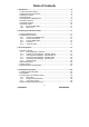
Table of Contents 1. Introduction .........................................................................................................8 1.1 Internet Access Features .................................................................................8 1.2 Advanced Internet Functions ...........................................................................8 1.3 Wireless Features............................................................................................9 1.4 LAN Features...................
. Configuring Your Wireless Router - Basic Functions ...................................27 5.1 Setup .............................................................................................................27 5.1.1 Configure Setup Parameters..............................................................27 5.2 Global Address ..............................................................................................28 5.2.1 Setup Global Addresses ........................................................
.6 MAC Clone ....................................................................................................47 6.6.1 Clone the MAC Address .....................................................................47 7. Troubleshooting ................................................................................................48 7.1 General Problems..........................................................................................48 7.2 Internet Access ............................................
List of Figures Figure 1: Network Connection................................................................................... 8 Figure 2: Front Panel............................................................................................... 10 Figure 3: Rear Panel ............................................................................................... 11 Figure 4: Installation Diagram .................................................................................
Figure 44: Popular Applications Feature ................................................................. 45 Figure 45: DMZ Host Screen .................................................................................. 47 Figure 46: MAC Clone Screen ................................................................................
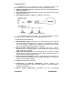
1. Introduction Congratulations on the purchase of your new Wireless Router. The Wireless Router is a multi-function device providing the following services: a) Wireless LAN Access Point for equipment compliant with the IEEE802.11b (DSSS) specifications. b) Shared Broadband Internet Access for both LAN (Ethernet) and WLAN (Wireless LAN) users. c) 4-Port Switching Hub for 10BaseT or 100BaseT connections.
c) d) e) f) g) connections or port numbers are normally blocked by the Firewall. The ability to define and allow such applications is provided, to enable such applications to be used normally. Virtual Servers. This feature allows Internet users to access Internet servers on your LAN. The required setup is quick and easy. DMZ. One PC on your local LAN can be configured to allow unrestricted 2-way communication with Servers or individual users on the Internet.
1.6 Security Features a) Password Protected Configuration. Optional password protection is provided to prevent unauthorized users from modifying the configuration data and settings. b) Wireless LAN Security. WEP (Wired Equivalent Privacy) is supported, as well as Wireless access control to prevent unknown wireless stations from accessing your LAN. c) NAT Protection.
LED Status WAN On(Red) (Broadband) Blinking (Yellow) Function Connection to the modem attached to the WAN (Internet) port is established. Data is being transmitted or received via the WAN port. Connection is not active. Off 1.8.2 Rear Panel Figure 3: Rear Panel Port Default Button WAN port (10/100BaseT) 10/100BaseT LAN connections Power Input Function Reset to Default. This button can be used by holding this button down for 10 seconds. Connect the DSL or cable modem here.
2.2 Installation Instructions Figure 4: Installation Diagram 2.2.1 Choose an Installation Site Select a suitable place on the network to install the Wireless Router. Ensure the Wireless Router and the DSL/cable modem are powered off. For best Wireless reception and performance, the Wireless Router should be positioned in a central location with minimum obstructions between the Wireless Router and the PCs.
3. PC Configuration This Chapter details the PC Configuration required on the local ("Internal") LAN. For each PC, the following may to be configured: a) TCP/IP network settings. b) Internet access configuration. c) Wireless configuration. 3.1 Windows Clients This section describes how to configure Windows clients for: a) Internet access via the Wireless Router. b) Using the Wireless Router's Wireless Access Point. The first step is to check the PC's TCP/IP settings.
b) Select the TCP/IP protocol for your network card. c) Click Properties. You should then see a screen like the following: Figure 6: IP Address (Windows 95) d) Ensure your TCP/IP settings are correct as follows. Using DHCP To use DHCP, select Obtain an IP address automatically. This is the default Windows settings. Restart your PC to ensure it obtains an IP address from the Wireless Router.
On the DNS Configuration tab, ensure Enable DNS is selected. If the DNS Server Search Order list is empty, enter the DNS address provided by your ISP in the fields beside the Add button, then click Add. Figure 8: DNS Tab (Windows 95/98) 3.1.3 Checking TCP/IP Settings - Windows NT4.0 a) Select Control Panel - Network, and, on the Protocols tab, select the TCP/IP protocol as shown below. Figure 9:TCP/IP (Windows NT4.
b) Click the Properties button to see a screen like the one below. Figure 10: IP Address (Windows NT4.0) c) Select the network card for your LAN. d) Select the appropriate radio button - Obtain an IP address from a DHCP server or Specify an IP address as explained below. Obtain an IP address from a DHCP Server This is the default Windows setting. Using this is recommended. By default, the Wireless Router will act as a DHCP Server. Restart your PC to ensure it obtains an IP address from the Wireless Router.
Figure 11: Add Gateway (Windows NT4.0) The DNS should be set to the address provided by your ISP. Click the DNS tab. On the DNS screen, shown below, click the Add button (under DNS Service Search Order), and enter the DNS address.
Figure 12: Add DNS (Windows NT4.0) 3.1.4 Checking TCP/IP Settings - Windows 2000 a) Select Control Panel - Network and Dial-up Connection. b) Right click the Local Area Connection icon and select Properties. You should see a screen like the following.
Figure 13: Network Configuration (Windows 2000) c) Select the Internet Protocol (TCP/IP) for your network card. d) Click the Properties button. You should then see a screen like the following.
Figure 14: TCP/IP Properties (Windows 2000) e) Ensure your TCP/IP settings are correct as follows. Using DHCP To use DHCP, select the radio button Obtain an IP Address automatically. This is the default Windows settings. Restart your PC to ensure it obtains an IP address from the Wireless Router. Using a fixed IP Address ("Use the following IP address") If your PC has already configured, make sure the correctness of IP Address and Subnet Mask on the General tab.
Figure 15: Network Configuration (Windows XP) c) Select the Internet Protocol (TCP/IP) for your network card. d) Click the Properties button. You should then see a screen like the following.
Figure 16: TCP/IP Properties (Windows XP) e) Ensure your TCP/IP settings are correct as follows. Using DHCP To use DHCP, select the radio button Obtain an IP address automatically. This is the default Windows settings. Restart your PC to ensure it obtains an IP address from the Wireless Router. Using a fixed IP address ("Use the following IP address") If your PC has already configured, make sure the correctness of IP Address and Subnet Mask on the General tab.
b) Use the following procedure to configure your Browser to access the Internet via the LAN, rather than by a Dial-up connection. For Windows 9x/2000 a) Select Start Menu - Settings - Control Panel - Internet Options. b) Select the Connection tab, and click the Setup button. c) Select "I want to set up my Internet connection manually, or I want to connect through a local area network (LAN)" and click Next. d) Select "I connect through a local area network (LAN)" and click Next.
3.3 Linux Clients To access the Internet via the Wireless Router, it is only necessary to set the Wireless Router as the "Gateway". Ensure you are logged in as "root" before attempting any changes. Fixed IP Address By default, most Linux installations use a fixed IP address. If you wish to continue using a fixed IP address, make the following changes to your configuration. a) Set your "Default Gateway" to the IP address of the Wireless Router. b) Ensure your DNS (Name server) settings are correct.
or Netscape Navigator version 4.7 or later. 4.1 Collecting ISP Information You will need to find out some information from your ISP before you can configure your Wireless Router, such as: a) Has your ISP assigned you a static IP address, or will they assign one to you dynamically? If they have given you a static IP, what is it? b) Does your ISP use PPPoE? If so, what is your PPPoE username and password? Call your ISP if you’re not sure of the answers to these questions. 4.
4.3.3 If you can't connect If the Wireless Router does not respond, check the following. a) The Wireless Router is properly installed, LAN connection is OK, and it is powered on. You can test the connection by using the "Ping" command: Open the MS-DOS window or command prompt window. Enter the command: ping 192.168.62.1. If no response is received, either the connection is not working, or your PC's IP address is not compatible with the Wireless Router's IP address. See the next item.
Type “admin” in the User Name field. Then, type a password and click OK. The default password is 1234. c) The Wireless Router Admin Tool will appear. Note that the web-based Admin Tool will log you out after a certain period of idle time. If this happens, you will need to re-enter your user name and password. 5. Configuring Your Wireless Router - Basic Functions Basic administrative functions include Setup, Global Address, Wireless, Tools, Status, DHCP, Log , and Statistics. 5.
d) Review the LAN IP Address information and change if necessary. These fields show the Device IP Address and Subnet Mask as seen by others on your Local Area Network (LAN). Most users will not need to change these values. Note that if you change the LAN IP address with the DHCP server running, you will need to restart your client machines. If you change the LAN IP address without the DHCP server running, you will need to manually reconfigure your clients' IP addresses.
Figure 20: Global Address Screen 5.2.1 Setup Global Addresses a) Review the first line in the table. It shows the default WAN IP address (specified in the Setup screen). If your ISP assigns you an IP address automatically, that address will be shown here. b) In the spaces provided for lines 2 - 8, list up to seven additional static and external IP addresses provided by your ISP. c) Click Apply when you finish choosing your settings, or click Cancel to undo your changes. 5.2.
Figure 21: Wireless Screen 5.3.1 Configure the Basic Wireless Options a) First, choose to Enable or Disable wireless access. None of the Wireless Router’s wireless functions will work unless you choose Enable. b) Type in the Extended Service Set Identifier (ESSID). The ESSID is the unique identifier shared by all the clients in a wireless network. It is case-sensitive and cannot exceed 32 characters. c) Type the Channel number. The Channel field specifies the default IEEE 802.
Figure 22: Set WEP Keys Window b) In the Set WEP Keys window, select the Encryption Level (64 Bit or 128 Bit). Note that although 128 Bit encryption uses a more secure encryption algorithm, it can slow down your network’s data transmission rates. c) Specify WEP keys by entering a Passphrase and clicking Generate, or by manually typing up to four keys. Use the Clear Keys button to delete any unwanted key information.
5.3.4 Configure the Advanced Wireless Options Most users will not need to configure the advanced wireless options. Note that the default values for the advanced wireless settings are shown in a table on the right-hand side of the screen. Figure 24: Defaults for Advanced Wireless Settings a) Review the FirmWare Version. This value tells you the version number of the wireless firmware you are currently using. b) Type a Beacon Interval.
changes. 5.4 Tools Use the Tools screen to: a) Change the administrative password for your Wireless Router. b) Restore the factory default settings. c) Perform a firmware upgrade. We strongly recommend that you change the password once you have accessed the Wireless Router for the first time. The Tools screen is shown in the figure below. Figure 25: Tool Screen 5.4.1 Change the Administrative Password a) Type in the Old Password. The factory default password is 1234. b) Enter a New Password.
b) Click OK. All your Wireless Router’s settings will be restored to their factory default values. Note that restoring the factory defaults will reset all of the Wireless Router’s settings in every screen. Once you have restored the factory defaults, you will have to re-configure the Wireless Router settings from scratch. Because of this, write down all your settings before restoring the defaults. 5.4.
Figure 28: Status Screen The displayed data may include: a) b) c) d) e) Host Name Domain PPPoE Login (Enabled or Disabled) LAN settings (IP Address and Subnet Mask) WAN ettings (IP Address, Subnet Mask, Default Gateway, and DNS information) To change any of these settings, go to the Setup screen. 5.5.1 DHCP Release and DHCP Renew If you chose the Dynamic IP and PPPoE Disable options in the Setup screen, you will see the DHCP Release and DHCP Renew buttons below the status information.
5.6.1 Setup the Wireless Router as a DHCP Server a) Make sure there is not already a DHCP server running on your network. b) Make sure that each computer on your network is configured to receive an IP address automatically. c) On the DHCP screen, click Enable. d) Type the IP Pool Starting Address. The address you specify will be the first IP address that can be assigned to a computer on the network. e) Type the IP Pool Ending Address.
Figure 31: Log Screen 5.7.1 Setup Logging on Your Wireless Router a) Click Enable for Access Log on the Log screen. b) Click Apply to put your changes in effect, or click Cancel to undo your changes. 5.7.2 Session Event Log Click Session Event Log to launch the Session Event Log window. In this screen, the Session Event Log Table lists session event entries. The table shows the Index number, Transport Type, Source IP, Source Port, Destination IP, Destination Port, and Terminate Reason for each event.
5.7.4 Intrusion Event Log Click Intrusion Event Log to launch the Intrusion Event Log window. In this screen, the Intrusion Event Log Table lists intrusion event entries. The table shows the Index number, Record Time, and Intrusion Type for each intrusion event. You can click Refresh to see the latest data. Make sure to close the window when you are finished looking at the log. The Intrusion Event Log is shown in the figure below. Figure 34: Intrusion Event Log Table 5.7.
Figure 36: Statistic The displayed data may include: a) LAN Statistics It showed receive and transmit data for LAN port. In addition, the Status, Max.Mb/s, IP Address, and MAC Address are listed above this table. b) WAN Statistics It showed receive and transmit data for WAN port. In addition, the Status, Max.Mb/s, IP Address, and MAC Address are listed above this table. c) AP Radio It showed receive and transmit data for AP Radio port. In addition, the Status, Max.
6. Configuring Your Wireless Router - Advanced Functions Advanced administrative functions include Virtual Servers, Filters, Special Apps, DMZ Host, and MAC Clone. The web-based Admin Tool allows you to set up advanced services and perform special functions, such as filtering or cloning your MAC address. Most users will not need to use these features. 6.
6.2.1 Setup a Computer on Your Network as a Virtual Server a) Select a Public IP Address from the drop-down list. Note that the IP address of any computer being used as a DMZ host will not appear in the list. b) Specify a Service Port. For help on which port to choose, refer to the Well-known Ports table on the right-hand side of the screen: Figure 40: Well-known Ports Table c) Select a Protocol (TCP, UDP, or Both) from the drop-down list. d) Specify the Private IP Address.
Figure 41: Filters Screen 6.3.1 To set up a filter: a) Select the Filtering Page from the drop-down list (1~12, 13~24, or 25~36). Note that you may define up to 36 filters. b) Select the Filtering Layer from the drop-down list, either Raw IP or Port Filtering. c) If you chose Raw IP, enter the Proto Num (the IP Protocol Number, between 0 and 255); otherwise, skip to Step d. Note that do not enter a Proto Num of 6 (TCP) or 17 (UDP), or the port filters will not work.
Figure 42: MAC Access Control Window b) Type the MAC address(es) that you want to block into the table. You can block up to 80 addresses. c) Click Apply at the bottom of the Filtered MAC Addresses list; then close the window. d) If you want to configure additional filtering options, go on to the procedure described in Section 0 6.3.3 Additional Filtering Options. e) If you are finished setting up your filters, click Apply to put your changes in effect, or click Cancel to undo your changes. 6.3.
Enabling this feature allows you to set up Network Address Translation (NAT). Enabling this feature allows you to protect your network with a Firewall firewall. Enabling this feature lets you access your Wireless Router’s Remote Management web-based admin tool through your WAN connection. IPSec Pass Enabling this feature lets you use IP Security Pass Through. Through PPTP Pass Enabling this feature lets you use Point-to-Point Tunneling Protocol (PPTP), used to enable VPN sessions.
Figure 43: Special Apps Screen 6.4.1 Configure Special Apps using the Popular Applications Feature a) Select the application you wish to enable from the Popular Applications drop-down list: Figure 44: Popular Applications Feature b) Choose a specific line in the table by selecting its number from the ID drop-down list. c) Click Copy to. The configuration settings for the selected application will appear in the table. d) Click Apply to put your changes in effect, or click Cancel to undo your changes. 6.4.
requests will be accepted. e) Choose Enable or Disable from the drop-down list for Session Chaining. This parameter specifies whether or not dynamic sessions can be chained, allowing multi-level session triggering. f) If you chose Enable in Step e, you may now choose Enable or Disable for Chaining on UDP; otherwise, skip to Step 7. g) Choose Enable or Disable from the drop-down list for Address Replacement. This parameter specifies whether or not binary address replacement should be performed.
Figure 45: DMZ Host Screen 6.5.1 Setup a DMZ Host a) Select a Public IP Address from the drop-down list. Note that the IP address of any computer being used as a Virtual Server will not appear in the list. b) Specify the Private IP Address. You only need to type the last part of the address; the first part is set automatically. c) Click Apply to put your changes in effect, or click Cancel to undo your changes. 6.5.2 To delete DMZ Hosts: a) For any DMZ Host you want to delete, select 0.0.0.
b) Click Mac Clone to put your changes in effect, or click Restore to undo your changes. 7. Troubleshooting This chapter covers some common problems that may be encountered while using the Wireless Router and some possible solutions to them. If you follow the suggested steps and the Wireless Router still does not function properly, contact your dealer for further advice. 7.1 General Problems Problem 1: Can't connect to the Wireless Router to configure it.
c) If the Wireless Router is configured correctly, check your Internet connection (DSL/cable modem etc) to see that it is working correctly. Problem 2: Some applications do not run properly when using the Wireless Router. Solution 2: The Wireless Router processes the data passing through it, so it is not transparent. Use the Special Applications feature to allow the use of Internet applications that do not function correctly. If this does solve the problem, you can use the DMZ function.
Problem 2: Wireless connection speed is very slow. Solution 2: The wireless system will connect at the highest possible speed, depending on the distance and the environment. To obtain the highest possible connection speed, you can experiment with the following. a) Access Point location. Try adjusting the location and orientation of the Access Point. b) Wireless Channel. If interference is the problem, changing to another channel may show a marked improvement. c) Radio Interference.
8.2 BSS/ESS 8.2.1 BSS A group of Wireless Stations and a single Access Point, all using the same ID (SSID), form a Basic Service Set (BSS). Using the same SSID is essential. Devices with different SSIDs are unable to communicate with each other. 8.2.2 ESS A group of Wireless Stations, and multiple Access Points, all using the same ID (ESSID), form an Extended Service Set (ESS). Different Access Points within an ESS can use different Channels.
If WEP is used, the Wireless Stations and the Access Point must have the same settings for each of the following. WEP Key WEP Authentication Off, 64-bit, 128-bit. For 64-bit encryption, the Key Table must match. For 128-bit encryption, the Key value must match. Open System, Shared Key, or both.
9. Specifications IEEE 802.3 (10BaseT) IEEE 802.3u (100BaseTX) IEEE 802.11b (Wireless) CSMA/CD Protocol 5 Ethernet: Ports 4 * 10/100BaseT RJ-45 port for LAN (excluding 1 shared) 1* 10/100BaseT RJ45 port for WAN 10BaseT: UTP Category 3 or better Cabling Type 100Base-T: UTP Category 5 or better WAN: 100 Speed (Mbps) LAN: 10/100 Wireless: up to 11 Wireless Operating Range Indoor: Up to 60M @11Mbps Up to 80M @5.5Mbps Up to 130M @2Mbps Up to 150M @1Mbps Outdoor: Up to 250M @11Mbps Up to 350M @5.