AW100 Series CDMA2000 1xRTT and 1xEV-DO IP Radio Access Network (IP-RAN) Installation and Maintenance Manual Version # 0.4 April, 2010 Prepared By AirWalk Communications, Inc. 1830 North Greenville Ave Richardson, TX, 75081 Phone: (972) 638-9400 Fax: (972) 638-9401 www.airwalkcom.
AW100 Series System Installation Manual ____________________________________________________________________________ Revision History Version Date Person 0.1 0.2 0.3 0.4 07/24/2009 10/07/2009 12/2/12009 4/7/2010 R MacLennan N. Kafai N. Kafai A Cho Description Initial Draft Document for review Addition on Introduction Edited Specifications Edited Technical Specs Revision Numbering Key 0.x 1.0 1.x 2.
AW100 Series System Installation Manual ____________________________________________________________________________ Table of Contents TABLE OF CONTENTS .................................................................................................................................. 3 1 INTRODUCTION ..................................................................................................................................... 5 1.1 1.2 1.3 1.4 1.5 1.6 2 PROPRIETARY INFORMATION NOTICE ..............
AW100 Series System Installation Manual ____________________________________________________________________________ 5.4 5.5 6 POWER SUPPLY WIRING (DC POWERED MODELS)............................................................................. 28 GPS ANTENNA CABLE WIRING.......................................................................................................... 30 FREQUENCY SETTING PROCEDURES .......................................................................................... 31 6.
AW100 Series System Installation Manual ____________________________________________________________________________ 1 INTRODUCTION 1.1 Proprietary Information Notice THIS DOCUMENT IS THE PROPERTY OF AIRWALK COMMUNICATIONS, INC. THE RECIPIENT MAY USE IT ONLY FOR THE PURPOSE FOR WHICH IT WAS TRANSMITTED AND WILL BE RETURNED UPON REQUEST OR WHEN NO LONGER NEEDED BY RECIPIENT. IT MAY NOT BE COPIED OR COMMUNICATED WITHOUT THE WRITTEN CONSENT OF AIRWALK COMMUNICATIONS, INC. 1.
AW100 Series System Installation Manual ____________________________________________________________________________ 1.6 Telecom Standards [1] 3GPP2 C.S0001 – 0006 Radio Interface Specifications for cdma2000 Spread Spectrum System [2] 3GPP2 X.S0013 – IMS/MMD Specifications [3] 3GPP2 A.S0013-C Interoperability Specification (IOS) for cdma2000 Access Network Interfaces – Part 3 Features [4] 3GPP2 A.
AW100 Series System Installation Manual ____________________________________________________________________________ [29] 3GPP2 C.20000.5-D, Upper Layer (Layer 3) Signaling Standard for cdma2000 Spread Spectrum Systems, March 2004 [30] IS-707-A-2, Data Service Options for Spread Spectrum Systems, March 2001 [31] TIA/EIA/IS-856-A, cdma2000 High Rate Packet Data Air Interface Specification, Mar 2004 [32] C.
AW100 Series System Installation Manual ____________________________________________________________________________ 2 AW100 Safety and Compliance Information 2.1 Statement of Intent The AirWalk AW100 Series IP-RAN is intended for use in a CDMA cellular infrastructure radio access network. The responsible body shall be made aware that, if the equipment is used in a manner not specified by the manufacturer, the protection provided by the equipment may be impaired. 2.
AW100 Series System Installation Manual ____________________________________________________________________________ 2.3 Maintenance Information 2.3.1 Cleaning The AirWalk AW100 units are protected by a high performance paint which does not require normal maintenance. If paintwork is soiled, it can be cleaned using a damp cloth after AC power has been disconnected. Do not use liquids or spray cleaning substances on the unit, since property damage or personal injury may result. 2.3.
AW100 Series System Installation Manual ____________________________________________________________________________ 2.5 Regulatory Compliance Information The FCC regulatory compliance information provided in this section is applicable only to models equipped with an FCC Identification Number (FCC ID). IP-RAN Base Station Model : AW100xxxxxxx FCC ID : R4Hxxxxxxxx S/N : 50.0 mm XX0000X DC IN: 12 VDC / 8A AirWalk Communications., Inc Contact: +1-972-638-9400 Made In U.S.A. 76.
AW100 Series System Installation Manual ____________________________________________________________________________ 3 AW100 System Introduction 3.1 Overview This document describes the AW100 IP-RAN products developed by AirWalk Communications Inc. The AirWalk AW100 Series is compact, standards compliant, optimal channel capacity, cost effective, and reliable cellular access point designed to provide improved mobile coverage and capacity enhancements for the CDMA mobile operators.
AW100 Series System Installation Manual ____________________________________________________________________________ • AW100-DO • This product is designed specifically for CDMA2000 1xEV-DO Rev. A networks.
AW100 Series System Installation Manual ____________________________________________________________________________ 3.2 AW100 Network Diagram The following diagram is typical network architecture for AW100-1X using IOS5.x standard interfacing to a CDMA softswitch network.
AW100 Series System Installation Manual ____________________________________________________________________________ The following diagram is typical network architecture for AW100-DO with connectivity to data core networks.
AW100 Series System Installation Manual ____________________________________________________________________________ 3.3 Hardware Configuration The AW00 Series IP-RAN is a unique combination radio and controller in one physical platform that is differentiated from other systems. Other systems have separate radio and controller platforms which add to cost and complexity in order to support CDMA2000 networks.
AW100 Series System Installation Manual ____________________________________________________________________________ Minicell Solution - Omni Medium Power Systems (up to 4W) - AW-100 Main Unit - 4W Slim Radio Unit (external RF power amplifier) - Optional DC RPSU for DC powered systems Pico / Enterprise Solution - Omni Low Power Systems (up to 200mW) - AW100 Main Unit 3.3.
AW100 Series System Installation Manual ____________________________________________________________________________ 3.4 System Capacities and Specifications 3.4.1 AW-100 Technical Specifications AW100 Specifications 1xEV-DO Rev A 1xRTT Picocell: 200mW / 23dBm Transmit Power Microell: 4W / 36dB External RU Macrocell: 20W / 43dB External RU RADIO Air Interface CDMA2000, 1xEV-DO Rev.
AW100 Series System Installation Manual ____________________________________________________________________________ 3.4.2 Radio Unit Technical Specification (Slim RU Series) Tx 1930 ~ 1950 MHz 1945 ~ 1970 MHz 1965 ~ 1990 MHz 869 ~ 894 MHz A/B/H Sub Bands available 43dBm, 20 Watt 53 ± 1.0dB 1.5: 1 43 ± 1.0dB Frequency Output Power Gain In/Out VSWR Coupling Value Attenuation Rx Freq.
AW100 Series System Installation Manual ____________________________________________________________________________ Mechanical Specification RF Input and Output Connector AC Power Connector RU Control Connector Weight SMA Female (Input) N Female (Output) IEC RJ-45 Serial Interface 13 kg (28.55 lbs.) 482mm(W) x 457mm(D) x 88mm(H) 19”(H) x 18”(D) x 3.5”(H) Dimensions ( W x H x D ) Per RU 2 Rack Units Table 3-2 Radio Unit Specifications (Slim RU Series) 3.4.
AW100 Series System Installation Manual ____________________________________________________________________________ 4 AW-100 Components 4.
AW100 Series System Installation Manual ____________________________________________________________________________ 4.2 Radio Unit (RU - Slim RU Series) The Slim RU series Radio Unit provides high power macrocell capabilities for the omni site configurations. The Radio Unit functions include a 4W or 20W power amplifier (measured at the antenna port), RF filtering for Tx and Rx paths, a duplexer function system, and a power supply. All components are packaged in a compact two rack unit package.
AW100 Series System Installation Manual ____________________________________________________________________________ 4.3 Optional DC RPSU (DC Power Configurations Only) DC powered Radio Unit (RU) systems are equipped with a separate DC power distribution unit which provides a single connection point for DC power source. Connections are provided for the 12v DC AW100 unit and the 27v DC Radio Unit. Front panel circuit breakers and voltage/current measurements are provided.
AW100 Series System Installation Manual ____________________________________________________________________________ 4.4 Component LED Configuration 4.4.1 CCPB- (Call and Channel Processing Board) LED status indicators are provided on the AW100 IP-RAN. LED functions are described in the following pictures and tables.
AW100 Series System Installation Manual ____________________________________________________________________________ 4.4.2 RU DC Power Distribution Unit (RPSU) [DC powered models only] The RU RPSU (DC Power Distribution Unit) is equipped with a digital voltmeter and digital ammeter as shown in Figure 4-13. Figure 4-13 RPSU DC Power Measurement Indicators (Front View) The following values are displayed on the front panel.
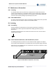
AW100 Series System Installation Manual ____________________________________________________________________________ 4.4.3 Radio Units Front Panel Indicators (Slim RU Series) The Radio Unit is equipped with indicators for power, communication activities and alarms. The location of the RU front panel indicators is shown in Figure 4-14 (each RU). PWR FLT MST SLV Figure 4-14 Radio Unit Front Panel Diagram A description of Radio Unit Front Panel indicator functions is shown in Table 4-2.
AW100 Series System Installation Manual ____________________________________________________________________________ 5 AW-100 Cabling 5.1 Power Supply Wiring (AC / DC Powered Versions) AC Power Supply The majority of the AW-100 systems will be powered via the AC/DC power supply. Connect the AW-100 main unit and if applicable the optional Radio Unit system to suitable AC power sources as shown in Figure 5-1.
AW100 Series System Installation Manual ____________________________________________________________________________ Common Rack Ground TOP VIEW Ground Points PWR 12VDC RUIF BSIF RUIF BSIF I D Setting POWER INPUT AREA 10M EVEN MasterSlave1 Slave2 G PS AN T TRX RXA RXB Test PSU ALM TX/RX_A ANT RF TX I N TX TP RF RX_A OUT RX_A TP RF RX_B OUT RX_B TP RX_B ANT Customer provided and installed ground cables Figure 5-2 Ground Wiring (shown with optional RU) 5.
AW100 Series System Installation Manual ____________________________________________________________________________ L SS405 Coaxial Cable Figure 5-4 AW-100 to RU RF Cable Specification Connect the external transmission lines from the diversity antenna systems to the RU Antenna connections as shown in Figure 5-3. External connectors are “N-Type”. Transmission line (or jumpers to transmission line) type and length will impact the overall link budget calculations for the cell site.
AW100 Series System Installation Manual ____________________________________________________________________________ Connect the RPSU main power bus to the external DC power supply system using the two-hole bolted connections as shown in Figure 5-6.
AW100 Series System Installation Manual ____________________________________________________________________________ 5.5 GPS Antenna Cable Wiring The AW-100 utilizes a 5.0V GPS system. GPS antennas can be ordered as optional equipment or supplied by customer. Connect the external GPS antenna RF cable to the “SMA” GPS antenna port on the AW-100 unit as shown in Figure 5-7. The GPS antenna must be located outdoors in a position to see the general sky.
AW100 Series System Installation Manual ____________________________________________________________________________ 6 Frequency Setting Procedures This section provided to meet regulatory requirements in certain jurisdictions which require local frequency setting procedures. Normally frequency settings should be made only in the iBSM system which will subsequently download them to the base station. Refer to the iBSM manuals for configuration and operating instructions. 6.
AW100 Series System Installation Manual ____________________________________________________________________________ 6.2.2 FA Change Procedure The AW-100 is consists of two different family of IP-RAN. AW100- 1xRTT The following menu driven commands permit local changes of the FA. Step 1 At the prompt enter the following: > pn3383 // this will take you to the menu screen similar to below: ================= PN 3383 ==================== 1. Tx Test 2. Rx Test 3. ParameterSetup 4. Rf Gain Display 5.
AW100 Series System Installation Manual ____________________________________________________________________________ // this will take you to the below menu screen. ================= XCVR SETUP ==================== 1. SET CHAN 2. SET TX ON 3. SET TX OFF -------------------------------------------------4. Show Channel 5. SHOW XCVR MODEL ID 6. SHOW XCVR STATUS 7. SHOW XCVR LEVEL 8. Show RSSI1 9. Show RSSI2 10. Show TSSI 11. Show RSSI1PWR 12. Show RSSI2PWR 13. Show TSSIPWR 14. Show XCVR Temperature 15.
AW100 Series System Installation Manual ____________________________________________________________________________ ALPHA : xcvrChangeCh Num [001 ~ 1500] [1175] [/0:Exit]==> Step 4 From the above menu, type the new channel desired (CDMA channels from 1 to 1500) and 0 to exit. Only standard CDMA channel numbers within the designated band capability of the radio is accepted by the base station.
AW100 Series System Installation Manual ____________________________________________________________________________ AW100- 1xEV-DO The following menu driven commands permit local changes of the FA. Step 1 At the prompt enter the following: > mpt32a // this will take you to the menu screen similar to below: ================================================ 1. Transmitter Test 2. Receiver Test 3. Parameter Setup 4. RF Gain Display 5. XCVR Setup 6. Turn Debug Messages On 7. Turn Debug Messages Off 0.
AW100 Series System Installation Manual ____________________________________________________________________________ 10. Show RSSI2 11. Show TSSI 12. Show RSSI1PWR 13. Show RSSI2PWR 14. Show TSSIPWR 15. Show XCVR Temperature 16. Show XCVR Reset Reason 17. Show XCVR Cable Status 18. Show XCVR PLL LOCK 19. Show XCVR Power Status 20. Show TX Status 0. Exit ===================================================== Step 3 Enter the following: Select Input Number => 1 // choosing 1 will take you to the below menu.
AW100 Series System Installation Manual ____________________________________________________________________________ 7 Installation Procedures This Section gives instructions for installing the AW100 Series IP-RAN and for connecting it to the wireless infrastructure. Always refer to the Cell Site Installation documents provided by the Project Engineer for the specific project. These instructions will include site specific installation requirements in addition to generic installation practices.
AW100 Series System Installation Manual ____________________________________________________________________________ 4) Determine when contacts are available for help (e.g.; Time of day, day of week.) for customer, installation teams and persons involved in the site planning. 5) Obtain any site access or security requirements (e.g.: ID Badges, Card-keys, Keys, Access codes) required to access installation site. 6) Locate the AirWalk IP-RAN equipment and any required support equipment.
AW100 Series System Installation Manual ____________________________________________________________________________ 3) +12 VDC Models require a rectified and filtered nominal 24V DC power source. Voltage can range from 22 VDC to 28 VDC to allow use with a float charged battery system. A designated 50A source with independent over current protection is required for each IP-RAN unit (fused or circuit breaker). No other equipment should be connected to the designated circuit breaker.
AW100 Series System Installation Manual ____________________________________________________________________________ 2) Any discrepancies or problems must be clarified and changes approved by the designated RF Systems Engineer prior to powering up any base station. 3) Locate the GPS antenna cables and verify the cable is equipped with a TNC connector for connection to the IP-RAN base station.
AW100 Series System Installation Manual ____________________________________________________________________________ 7.2 IP-RAN Installation Procedures 7.2.1 IP-RAN System physical installation 1) First, install any support shelves or brackets required to provide rear support. 2) Locate the correct holes and install the heaviest rack unit first, which will normally be the RU system. Installation normally requires at least two people to lift and locate the unit due to the heavy weight.
AW100 Series System Installation Manual ____________________________________________________________________________ 3) Connect the external GPS antenna to the IP-RAN GPS antenna input. Use a suitable RF cable (RG-58 or equivalent) equipped with a TNC connector. 4) Connect the external RF antenna systems. Follow site specific cable installation drawings prepared by the RF system/planning engineer for cable type and routing. The IP-RAN unit is equipped with N-type RF connectors.
AW100 Series System Installation Manual ____________________________________________________________________________ 5) Verify the Ethernet backhaul links are communicating by observing the activity indicators on the external Ethernet switch. The activity indicators are typically found on the front panel or adjacent to the connection point on Ethernet switches. The indicators should be flashing intermittently to indicate the presence of IP packet activity. 7.2.
AW100 Series System Installation Manual ____________________________________________________________________________ 7.3.1 Web Server Installation Tool Set-up The Web Server Installation Tool is built into the IP-RAN base station. Connection to the tool requires only a PC equipped with an Ethernet capability and a common browser such as Explorer.
AW100 Series System Installation Manual ____________________________________________________________________________ BSID number that will be used for the manufacturing default number. This number should be changed before the operation can begin. Use these default addresses to access the AW100 functions for the first time using the PC browser. Enter these IP addresses in the browser address bar to gain access to the AW100 functions.
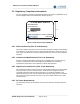
AW100 Series System Installation Manual ____________________________________________________________________________ 7.3.3 IP-RAN Initial Configuration (default “booting mode”) Connection the PC to the RN using either the default factory IP address (new systems), or the primary address or secondary address (systems already configured).
AW100 Series System Installation Manual ____________________________________________________________________________ Figure 7-4 IP-RAN Configuration Screen (default “booting mode”) 7.3.4 IP-RAN Re-Configuration (“running mode”) An IP-RAN equipped with an existing configuration can again be accessed via the Web Server tool to change parameters. The connection to the IP-RAN must be made using either the current primary IP address or the secondary address which is based on the base station id.
AW100 Series System Installation Manual ____________________________________________________________________________ Figure 7-6 IP-RAN Configuration Screen (“running mode”) Configuration changes are entered using this screen and accepted by the IP-RAN by clicking on the “Submit” button. However, the new changes will NOT become effective until the IP-RAN unit is rebooted. This can be done by clicking on the “Reboot” button.
AW100 Series System Installation Manual ____________________________________________________________________________ - Completion of the installation checklist - Final approval by the relevant customer authority 7.
AW100 Series System Installation Manual ____________________________________________________________________________ As a rule, 90% of component problems can be attributed to wiring and connector problems). a) Check cable b) Check connector c) Check for solid connection d) Check with site specific installation documentation 3) Make sure that all power cords are properly attached to each IP-RAN component. Be certain that all power cords are plugged into a functioning electrical outlet.
AW100 Series System Installation Manual ____________________________________________________________________________ 8 Appendix A - Acronyms Acronym 2G 3G AAA BHCA BSC BTS CA CALEA CDMA CPE CPU CSM5000 DC DHCP EVDO EVRC FA FCC FM FO GPS HLR HO HSS iBSM IF IMSI I-CSCF IOS IP IKE IMS IPSec LAN MG MN MS MSC MTBF PCF PSTN QCELP QOF QOF QoS RAN Description Second Generation in CDMA wireless network Third Generation in CDMA wireless network Authentication, Authorizing, and Accounting Busy Hour Call Attempts Bas
AW100 Series System Installation Manual ____________________________________________________________________________ Acronym Description RC RN RF RNC RPSU RTP RU SDU SMS SS SIP Radio Configuration Radio Node Radio Frequency Radio Network Controller Remote RF Power Supply Unit Real-Time Transport Protocol Remote RF Unit Selection and Distribution Unit Short Message Service Soft Switch Session Initiation Protocol S-CSCF Serving Call Session Control Function ______________________________________________
AW-100 Series System Installation Manual __________________________________________________________________________ 9 Appendix B - Installation Certification Document Date: ______________________________________________________ Subject: _________________________________________________ The subject AW-100 Series IP-RAN has been installed and proper system operation has been verified on this date.
AW-100 Series System Installation Manual __________________________________________________________________________ This Page Marks the End of this Document ____________________________________________________________________________ AirWalk Proprietary and Confidential Page 54 of 54 7/28/2010